ALL FLEX CIRCUITS AN OVERVIEW OF FLEXIBLE PRINTED CIRCUIT
Sinusoidal steady-state circuit inductive solar container
This chapter analyzes the steady-state system response, where all the switching transient responses are already damped and a fixed amplitude of voltage and current is reached. Under this condition, the equivalents of resistors, inductors, and capacitors are calculated.. Convert each of the following time-domain signals to phasor form. Convert the following circuit to the phasor domain. to the capacitor. Find the voltage across the capacitor, . The following voltage is applied to the inductor. Find the current through the inductor, . The input = current ⋅ is. . What is a sinusoidal steady state? In the sinusoidal steady state, every voltage and current (or force and velocity) in a system is sinusoidal with angular frequency ω. However, the amplitudes and phases of these sinusoidal voltages and currents are all different. How do inductors appear at. . (1) Generation, transmission, consumption of electric energy occur under sinusoidal conditions. (2) It can be used to predict the behaviors of circuits with non- sinusoidal sources. Need to work in the realm of complex numbers. What is the phase of a sinusoidal function? What is the phasor of a. . Following are some steps to analyze the circuit response (i.e., the voltage drops and current flows) under sinusoidal excitations. The first step is to determine the stage of the response. This means determining whether the response has reached a stable operation or its amplitude is changing due to. . Phasors may be used to analyze the behavior of electrical and mechanical systems that have reached a kind of equilibrium called sinusoidal steady state. In the sinusoidal steady state, every voltage and current (or force and velocity) in a system is sinusoidal with angular frequency ω. However, the. . In this unit, we consider circuits in which the sources are sinusoidal in nature. The review section of this unit covers most of section 9.1{9.9 of the text. The new material is almost exclusively contained in Chapter 10 of the text. 4.1 Review 4.1.1 Sinusoidal Sources Up to this point in the.
Read More
The control circuit is disconnected and energy cannot be stored
Once the lockout or tagout devices have been applied, all potentially hazardous stored or residual energy must be relieved, disconnected, restrained, and rendered safe before the servicing or maintenance can be conducted.. Employers must develop, document, and implement energy control procedures to control potentially hazardous energy and render equipment or machinery inoperative whenever employees perform activities covered by the Lockout/Tagout standard. The energy control procedure provides the authorized employee. . LOTO safety, also known as lockout/tagout (LOTO), is a critical practice for protecting workers from hazardous energy during maintenance or servicing of machines. Following OSHA standard 1910.147, companies must establish and enforce an energy control program that instructs employees follow the. . The lockout/tagout procedure provides guidelines to ensure individual safety of personnel servicing and maintaining equipment by preventing the inadvertent operation of equipment and providing protection from stored energy through the control of hazardous energy. Refer to 29CFR1910.147 and §.269. . Most electricians and technicians will agree working on electrical equipment that has been “de-energized,” i.e. no voltage, offers the greatest level of safety from electric shock and arc flash hazards. And while true, it’s only true in part. Take for example, the relatively common activity of. . The placement of a Lock Out device on an energy isolating device, in accordance with an established procedure, ensuring that the energy isolating device and the equipment being controlled cannot be operated until the lockout device is removed Lock Out Device A device that utilizes a positive means. . The purpose of this program is to prevent inadvertent operation or energization of machines, equipment, or processes in order to protect employees and establish methods for achieving zero energy state. This program applies to activities such as: erecting, installing, constructing, repairing.
Read More
Outdoor circuit breakers do not store energy
A circuit breaker does not store energy; rather, it serves as a device that provides automatic disconnection of electric circuits, ensuring safety by interrupting the flow of electricity during overloads or short circuits. 2.. How does a circuit breaker store energy? 1. A circuit breaker does not store energy; rather, it serves as a device that provides automatic disconnection of electric circuits, ensuring safety by interrupting the flow of electricity during overloads or short circuits. 2. However, certain circuit. . overed. Use a Ground fault circuit interrupter (GFCI). Keep products with line cords away from sinks, puddles, pools, ponds, and h t tubs. Keep outdoor outlets weather-protected with outlet prong. Dispose of electrical items and extension cords with damaged manual. Use goggles op ration. Exposed. . Traditional breakers waste 8-12% of transient energy during fault interruptions through heat dissipation. That’s enough to power 12 million smartphones annually—energy literally going up in smoke. As grid operators face tighter decarbonization targets, this oversight becomes harder to ignore. Since. . Circuit breaker installation plays a key role in making sure your electrical system works well. Local rules, weather, and how your home is built all matter when you choose the best spot. Pick indoor or outdoor circuit breaker spots for safety and ease. Local rules are important too. Indoor panels. . Circuit breakers play a crucial role in outdoor power equipment by providing essential protection against electrical overloads and short circuits. They act as safety devices, automatically shutting off power when excessive current is detected, preventing damage to the equipment and reducing the. . Ever wondered how your circuit breaker magically springs into action during a power surge? Spoiler alert: it’s all about energy storage retention. Think of it like a coiled spring in a jack-in-the-box—except here, the “pop” saves your equipment from damage. Circuit breaker energy storage retention.
Read More
No solar container required when closing the circuit breaker
Each PV system disconnecting means shall consist of not more than six switches or six sets of circuit breakers, or a combination of not more than six switches and sets of circuit breakers, mounted in a single enclosure, or in a group of separate enclosures.. Disconnecting means and wiring methods for solar installations must meet requirements specific to solar photovoltaic systems. A readily accessible disconnecting means is required to disconnect power from each PV system [690.13 (A) (1)]. Figure 01 The door or hinged cover for the PV system. . Means shall be provided to disconnect the PV system from all wiring systems including power systems, energy storage systems, and utilization equipment and its associated premises wiring. (A) Location. The PV system disconnecting means shall be installed at a readily accessible location. Where. . Important Safety Disclaimer: Wiring solar panels to a breaker box involves working with high-voltage electrical systems that can cause serious injury or death if handled improperly. This guide is for educational purposes only. Always consult with a licensed electrician for actual installations and. . I am in the very early stages of planning out a Hybrid solar system, this will be a single inverter, with Solar, Batteries and grid tied. I am planning to put my Inverter and Batteries in a garage, so they will not be accessible outside. What disconnects do I need to place outside? I am a little. . A solar disconnect switch is a critical safety device required in every photovoltaic system to protect installers, maintenance workers, and first responders. Under NEC Article 690.13, all solar installations must include readily accessible disconnect means that allow complete isolation of the. . Disconnecting means and wiring methods for solar installations must meet requirements specific to solar photovoltaic systems. A readily accessible disconnecting means is required to disconnect power from each photovoltaic (PV) system [690.13 (A) (1)], as shown in Fig. 1. Fig. 1. A readily.
Read More
Circuit breaker electrical equipment solar container principle
This article will explore what circuit breakers do in renewable energy systems, why they are critical in solar installations, how to choose and size the right breaker, types of breakers used (from small PV arrays to large wind turbines), safety and compliance factors . . Eaton offers the industry’s most complete and reliable circuit protection for PV balance of system, from fuses, fuse holders and circuit breakers to safety switches and surge protection—allowing for comprehensive overcurrent and overvoltage protection anywhere in the PV system. Eaton offers a range. . Circuit breakers designed for solar panel installations (foreground) must handle DC currents safely while protecting the photovoltaic arrays (background) from overloads and faults. Ensuring proper breaker selection and sizing is crucial to maintain safe and efficient solar power systems. Beyond. . Choosing the appropriate circuit breaker for a solar system is crucial for safety, reliability, and effectiveness. Where should a DC breaker be placed in a PV combiner box? Usually, according to European standards, circuit breakers of DC sides are put in the PV combiner box to protect every solar. . If you have breaker tripping, then shut off main power. Then, remove panel and inspect wires connecting solar breaker for being loose, disconnected, etc. If not there, then check junction box on roof for similar. Somewhere, a short is occurring. [pdf] Look for a breaker in the “off” position or. . Their compact design a?| Medium voltage breakers employ the principle of current-zero-interruption; means a zero crossing is required for the breaker to interrupt the current. In case of unfavourable generator parameters, the a?| (C) 2025 Embrace New Energy 2 / 5 Web:. . What are pvgardtm solar circuit breakers? PVGardTM solar circuit breakers are part of a product family that combines a disconnect with overcurrent protection in one device to protect photovoltaic systems. PVGard breakers can also be used as a disconnect means in combiner box and inverter.
Read More
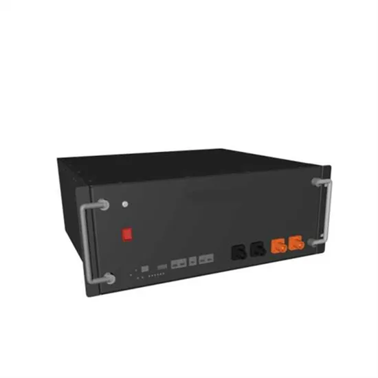
Solar container battery bmu circuit
The functions of BMU include providing real-time monitoring function of voltage and temperature of a single battery (single cell), thermal management and equalization ability, and communication with the main control module of superior battery cluster through CAN bus to form. . This reference design is a full cell-temperature sensing and high cell-voltage accuracy Lithium-ion (Li-ion), lithium iron phosphate (LiFePO4) battery pack (32s). The design monitors each cell voltage, cell temperature, and protects the battery pack to secure safe use. This design uses an onboard. . A battery management system (BMS) is a critical component of all electric vehicles. It is responsible for making sure the battery doesn’t explode. To fully understand a BMS, we need to understand battery cell chemistry, we’ll go into that briefly, we’ll go into the functions of a BMS briefly, and. . An end-to-end approach to Design and Verify BMS: from Requirements to Virtual Field Testing An end-to-end approach to Design and Verify BMS: from Requirements to Virtual Field Testing Conrado Ramirez MathWorks Irina Costachescu NXP Marius Andrei NXP Carlos Villegas Speedgoat Agenda •System-level. . The battery management unit is part of the battery management system and is installed on the battery module (pack). The functions of BMU include providing real-time monitoring function of voltage and temperature of a single battery (single cell), thermal management and equalization ability, and. . NXP HVBMS reference design is a scalable ASIL D architecture for high-voltage applications, composed of three modules: Battery Management Unit (BMU), Cell Monitoring Unit (CMU) and Battery Junction Box (BJB). The BMU board features the recently launched automotive safety integrity level (ASIL) D. . As utility-scale Battery Energy Storage Systems (BESS) expand across the world, the Battery Management System (BMS) has become the critical safety layer protecting every cell, module, rack, and container. Modern BMS design integrates BMUs, BCUs, balancers, insulation monitoring, SoC/SoH.
Read More