API 650 CONE ROOF STORAGE TANK ERECTION JACKING METHOD
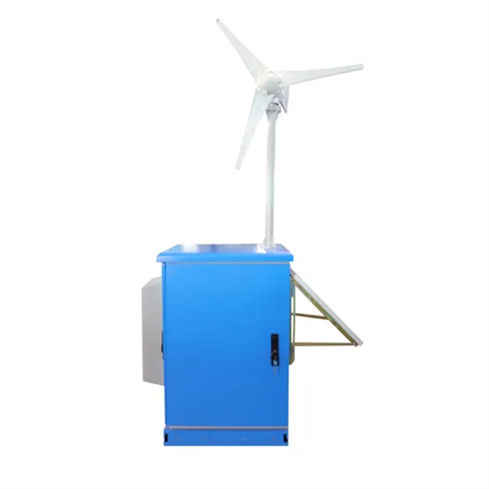
Illustration of solar container tank pressure regulation method
Pumping to a storage tank (A) with a direct-drive solar pump provides a few extra days of above-ground water. The install shown here uses the solar/battery powered Tankless Pressure Pump™ or TPP (C) to pressurize water from the storage tank, replacing the need for a. . A reverse action pressure switch dropped into the pipeline to sense changes in pressure from the mechanical float valve. The reverse action pressure switch is still hardwired into the charge controller (shown underneath the solar panels), but is placed closer to the pump and therefore uses. . Protectoseal vents are intended for use on atmospheric and low pressure liquid storage tanks. This section explains why tank venting equipment is needed and the method of sizing and specifying relief vents. The hazards associated with pressure and vacuum accumulation, especially in tanks storing. . Experience with the design of pressure relief systems on such vessels has shown that the design and basis of safety for pressure relief of atmospheric tanks is often misunderstood leading to situations where the tank may be subjected to pressures outside of the design limitations. This paper. . Pressurized solar tanks shall comply with applicable requirements in Chapter 3 of this document and at least one appropriate base standard (s) referenced in Table 401.1. Once selected, the solar tank shall comply with all applicable requirements and tests from the selected base standard as modified. . These guidelines have been produced for the safe loading and unloading of standard UN PORTABLE TANK CONTAINERS. NOTE: These tanks often carry hazardous product and the operator should exercise extreme care when handling tank containers. 1. Loading and Unloading 2. Methods of loading 3. Methods of. . The closed expansion vessel with membrane consists of a closed container divided into two parts by a membrane which separates water from gas (nitrogen or air) and which acts as an expansion compensation device. After the temperature of the medium increases, the pressure inside the vessel keeps.
Read More
Solar container tank hydraulic station installation method
This document provides a method statement for tank installation. It outlines the scope, references, and general procedures for preparing the site, welding, and Oil tank installation requires absolute precision.. Please read this installation manual thoroughly and in detail in order to be able to fully exploit the functionality of the product. DualSun disclaims all liability for defetcs and damages that would result from non-compliance with the installation instructions (improper use, incorrect. . mpact solar assembly can be wall mounted. SOKI comprises all comp nents required for the hydraulic circuit. To minimise thermal losses, the SOK return, as well as an optical flow meter. An integral non-return valve prevents the undesirable thermo-siphon effect, i.e. the solar buffer tank does not. . Improper installation, adjustment, alteration, service and use of this unit can result in serious injury. This unit must be installed by a professional installer. The installation must comply with all national, state and local plumbing and electric codes. Proper installation is the responsibility. . A Mobile Solar Power Container is a self-contained, transportable solar energy system built into a shipping container or customized enclosure. Designed for flexibility, rapid deployment, and This document provides a method statement for tank installation. It outlines the scope, references, and. . during the off-peak months. Evacuated Tube Solar Thermal Collectors are able to capture the available Solar Energy and then transfer it as Thermal Energy to the water heating system, thereby raising the temperature in the hot water storage cylinder, and offsetting the reliance to on alternative. . SolarStation HX and place the assembly on the side of the tank. The side of the SolarStation HX should be 1” to the left of the top electric cover. The bracket should lie flat on the top of the tank. Scribe the tank to match the bracket location (Figure 2.1.1). Page 7 To the extent possible, slide.
Read More
Can the car key be placed in the battery storage tank
No, leaving a smart key inside the car does not significantly affect its battery life. Smart keys use very little power when not in use. The primary function of a smart key is to communicate with the vehicle’s system, which happens sporadically.. When you leave your key fob inside your car, you may wonder: Does it drain the car battery? It’s a common concern many people have, especially with keyless entry and push-start systems becoming more popular in modern vehicles. In this article, we’ll dive deep into how key fobs work, whether leaving. . Will a faraday box/cage drain my car key fob battery? I have a 2012 Toyota Rav-4, I use the original key fob to the car and I have a spare. The car is push to start (keyless) and this morning it wasn’t recognizing that the key was in the car, so I couldn’t start it. The fob has also been slow to. . If it turns out that storing your key fob next to your cell phone each night as it charges eventually causes the key fob battery to fail prematurely, then maybe consider moving the key away from your phone- but I wouldn't necessarily do that unless you experience a problem. The key fob battery is. . Leaving a key in the car drain battery is a common mistake that can have severe consequences. When a key is inserted into the ignition and the car is turned off, it can cause the battery to drain slowly over time. This can lead to a range of problems, from a weak battery to complete battery. . But is it possible that your key fob is the culprit when it comes to your dead battery? “A key fob will constantly try to communicate with the car. And that does cause a slight drain on the battery, but generally that won’t completely drain a healthy car battery,” says Mike Monticello, Consumer. . A parasitic key fob left inside a car could be silently draining the battery, a concern highlighted by TikTok mechanic Brandon Sloan (@performancetransmission). In a video posted on November 12, Sloan explains the risks of leaving your key fob inside your car, and shows why Yukon models are.
Read More
Stockholm buffer storage tank
Manufacturer of horizontal and vertical chilled water buffer tanks for chiller applications. Features include pressure vessels, internal baffles, thermal insulation, installation legs, and air vents. Serves the plumbing and heating systems industries. Meets ASME and ANSI. . What is a buffer tank in a heating system? The principle of a buffer tank in a heating system is to store heat and use it later when demand is higher or energy availability is favorable. Here are the basic principles of buffer tank operation in a heating system: Heat accumulation. Heating system. . Buffer tank The tank that makes all the difference. The BuffMax from Thermo 2000 is a 3-in-1 solution that acts as a buffer tank, storage tank and hydraulic separator. It is recommended to optimize the performance of several different types of heating systems: low-mass boilers, biomass systems. . Amtrol ASME Buffer Tanks add capacity to non-potable, closed systems to help reduce cycling, improve temperature control and provide more consistent system operation. Available for chilled water and hot water applications. All Amtrol Buffer Tanks are made at our ISO 9001:2015 registered facilities.. A chilled water buffer tank is ideal for chillers with insufficient water volumes. It adds volume to help your water system buffer, preventing erratic system operations. These tanks increase the capacity of a closed loop chilled water system and stabilize the return water temperature. This results. . In the realm of HVAC systems, buffer tanks play a crucial role in optimizing performance and energy efficiency. These versatile components are designed to store thermal energy, ensuring a steady supply of hot or cold water when demand fluctuates. A buffer tank, also known as a thermal storage tank. . specialist company. This container has been manufactured with the utmost care and has undergone a leak test on the flanges and plugs before eaving the factory. However, this does not release the constructor of the system from their duty of care to include the container in the leak test (not a.
Read More
Working principle of air energy high pressure liquid storage tank
Step 1 is the charging process whereby excess (off-peak and cheap) electrical energy is used to clean, compress, and liquefy air. Step 2 is the storing process through which the liquefied air in Step 1 is stored in an insulated tank at ∼ 196°C and approximately. . The working air is deeply cooled down through the cryo-turbines or throttling valves, the liquid air is finally produced and stored in a liquid air tank. The cryogenic tank is designed with vacuum insulation similar to the normal liquid nitrogen tank. Does liquid air energy storage use air?. During charging, air is refrigerated to approximately -190 °C via electrically driven compression and subsequent expansion. It is then liquefied and stored at low pressure in an insulated cryogenic tank. To recover the stored energy, a highly energy-efficient pump compresses the liquid air to. . Capacity defines the energy stored in the system and depends on the storage process, the medium and the size of the system;. Power defines how fast the energy stored in the system can be discharged (and charged);. Efficiency is the ratio of the energy provided to the user to the energy needed to. . sky method due to maintaining a high pressure. While LH 2 storage provides an optimal density, it is inherently volatile and requi es significant en salt thermal energy storage system is used. The p wer cycle has steam at 574°C and 100 bar. The condenser is air-cooled. . of similar temp. . Abstract : Liquid air energy storage is a new generation of air energy storage system that uses a liquefied air stored in a cryogenic liquid storage tank to form a potential energy reserve. Using Aspen HYSYS software to realize the simulation analysis of the combined process and independent process. . The paper offers a succinct overview and synthesis of these two energy storage methods, outlining their core operational principles, practical implementations, crucial parameters, and potential system configurations. The article also highlights approaches to enhance the efficiency of these.
Read More
Illustration of solar container capacitor storage method
Schematic illustration of typical electrochemical energy storage system A simple example of energy storage system is capacitor. Figure 2(a) shows the basic circuit for capacitor discharge. Here we talk about the integral capacitance. The called decay time. Fig 2.. A capacitor is a passive electronic component that stores energy in an electric field. It consists of two conductive plates separated by an insulating material known as a dielectric. When a voltage is applied across the plates, electric charge accumulates, allowing the capacitor to temporarily. . Capacitors exhibit exceptional power density, a vast operational temperature range, remarkable reliability, lightweight construction, and high efficiency, making them extensively utilized in the realm of energy storage. There exist two primary categories of energy storage capacitors: dielectric. . Schematic illustration of typical electrochemical energy storage system A simple example of energy storage system is capacitor. Figure 2(a) shows the basic circuit for capacitor discharge. Here we talk about the integral capacitance. The called decay time. Fig 2. (a) Circuit for capacitor discharge. . Capacitor solar energy storage, often referred to as supercapacitors, is a revolutionary technology designed to address the challenges of solar energy intermittency. Unlike traditional battery systems, which store energy in chemical form, capacitors store energy electrostatically. They consist of. . The prospects for capacitor storage systems will be affected greatly by their energy density. An idea of increasing the “effective” energy density of the capacitor storage by 20 times through combining electronic circuits with capacitors was originated in 1992. The method, referred to as ECS. . Tired of EU grid voltage drops from inductive loads? BESS Container in EU Grid Reactive Power Compensation delivers 20ms reactive power support, cuts costs by 35% vs. capacitor banks, and a?| During the handover of the fully installed solar container energy plant at Elundini Primary School, our.
Read More