CHAPTER 6 INDUCTANCE CAPACITANCE AND MUTUAL INDUCTANCE
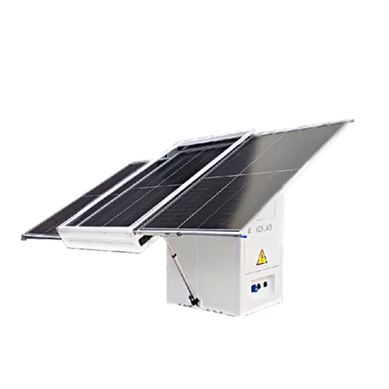
Mutual inductance components also serve as solar container components
Set to redefine efficiency and sustainability, bidirectional microinverters work in conjunction with solar panels, battery-based energy storage systems, and the electric grid to provide nonstop reliable power while maximizing the return on investment for solar installations.. have a mutual inductance of M. This mutual inductance might be positive or negative, depending on the dotted terminals and the current direction, which also determines the y can be stored in an inductor. The role played by an inductor in the magnetic case is analogous to that of a capacitor in. . Now, by varying I1 with time, there will be an induced emf associated with the changing magnetic flux in the second coil: 21 is called the mutual inductance. It can also be written as of the two coils such as the number of turns and the radii of the two coils. In a similar manner, suppose instead. . Mutual inductance in energy storage systems can be calculated using the following principles: 1. Definition of mutual inductance, 2. Mathematical formula for mutual inductance, 3. Dependency on physical parameters, 4. Applications in energy storage systems. Extensive analysis of the second point. . That’s mutual inductance—the principle behind transformers, wireless charging systems, and many communication circuits. In practice, applying mutual inductance is not as simple as the textbook diagrams suggest. Engineers often face challenges such as estimating coupling in irregular geometries. . What is the inductance of a coil? An inductor is a passive component, which, as an AC resistance, produces a counter-voltage, the self-induction voltage. The inductance (L) of the coil is dependent on the core material, the geometry of the core material, the winding turns and the type of windings.. here we will discuss the remaining 2 types of basic elements: inductors, capacitors. but store energy. and derivative of time, thus more complicated than resistors. L ? i C dv ? , respectively? coil. The resulting magnetic field B ( r ) N is the permeance. 1 1 . which describes how easy a coil.
Read More
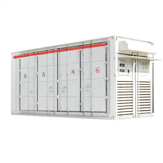
Push-pull solar container inductance calculation
Measure the inductance of the the inductor/material. Next, determine the current. Measure the current running through the inductor. Finally, calculate the inductor energy. Calculate the total energy stored using the equation above.. del the system and derive the transfer function. In this paper,state space averaging technique is used to model the push-pull converter t s and motor drives is designed and investigated. The emphasis is to obtain a ripple f are the main features of the isolated converter. This paper proposes. . Ever wondered why your push-pull converter keeps hiccuping like a caffeinated hamster? The answer might lie in your energy storage inductor calculation. Whether you’re designing a solar inverter, an EV charger, or just trying to impress your engineering buddies, mastering this skill is. . What primary inductance value should I choose for my push-pull power supply design using SN650x devices? SN650x devices are push-pull transformer drivers and the push-pull topology doesn't have a direct dependency on primary inductance of a transformer as a design parameter. The design requires. . Push-pull energy storage inductor calculation current in an inductor can not change instantly, the voltage across the inductor will adjust to hold the current constant. The input end of the inductor is forced negative in voltage by the decreasing current, eventually reaching the point where the. . How do you calculate energy stored in an inductor? C. The formula to calculate the energy stored in an inductor is W = 1 2 L I 2, where 'W' denotes energy stored (in joules), 'L' denotes inductance (in henries), and 'I' denotes current (in amperes). D. The formula to calculate the energy stored in. . I am designing my first voltage-fed push-pull converter, and I got stuck during the transformer sizing process. I am not exactly sure how to proceed. I have determined the primary and secondary peak currents, as well as the number of turns, but I don't know what to do next. How can I accurately.
Read More
Switching power supply solar container inductance is too large
A larger inductor builds up current more slowly when the same voltage is applied accross it. Therefore, if you need a lot of current you have to use a smaller inductor to build up current more quickly, or leave the switch on longer to build up more current.. Improper inductor sizing and violation of the inductor saturation current rating can cause a wide variety of issues within DC-to-DC converters, two of which are audible ringing and overheating. This article is the first in a series where common switch-mode power supply (SMPS) design errors will be. . The peak-to-peak value is determined by the various input and output voltages, switching frequency, duty cycle and inductor. The first figure shows a buck converter. The second shows the waveforms of the buck converter. It shows the switch S, the voltage across the inductor and the current through. . Design limitations: The most important limiting factors in inductor design are (a) temperature rise and efficiency considerations arising from core losses and ac and dc winding losses, and (b) core saturation. Output filter inductors (buck-derived) --single and multiple windings are seldom operated. . Inverters are switched off during a blackout and make that you have electricity on your roof while being without it in your home. This may not be as urgent where you live, but in countries like Mexico, blackouts are more common. In such a case, I want to be able to use the electricity from the. . A supposedly simple process can turn out to be much more complicated than expected, and the range of allowable inductors is found to be quite large. Five or six times a year, I teach a class in power supply design to 30 working engineers. One of the design examples involves a buck converter, and. . The inductance value, measured in henries (H), determines the inductor’s ability to store energy. A higher inductance value means more energy storage but can also result in a larger physical size. Therefore, achieving the right balance between inductance value and physical dimensions is essential.
Read More
What is the solar container inductance of the dc module
Simplified formula (single-phase full bridge): L approx frac {V_ {dc} times (1-D)} {2 times f_s times Delta I_L} Where: V_ {dc} is the DC bus voltage, D is the duty cycle, and Delta I_L is generally 10%-30% of the rated current.. Power inductor specifications typically include inductance value (mH),rated current (A),saturation current (A),and DCR (mO)as the main parameters. Inductors,as key components in electronic circuits,can be classified into various types based on structure,manufacturing process,and application. . Simplified formula (single-phase full bridge): L approx frac {V_ {dc} times (1-D)} {2 times f_s times Delta I_L} Where: V_ {dc} is the DC bus voltage, D is the duty cycle, and Delta I_L is generally 10%-30% of the rated current. Simplified formula (single-phase full bridge): L approx frac {V_ {dc}. . Understanding the energy storage inductance of a direct current (DC) module is vital for enhancing efficiency and functionality in various electrical and electronic applications. 1. Energy storage inductance represents the ability of a module to store energy in an inductor; 2. This parameter is. . del the system and derive the transfer function. In this paper,state space averaging technique is used to model the push-pull converter t s and motor drives is designed and investigated. The emphasis is to obtain a ripple f are the main features of the isolated converter. This paper proposes. . The assembly of the panels will be on the so-called bridges on the roof are made of trapezoidal sheet metal, so the bridges will be interconnected with a PE cable and then "grounded". In the drawings, PE is marked in yellow. All cables will be run side by side, tied together with cable ties and. . emaining 2 types of basic elements: inductors, c rical capacitance is an integral parameter in electronics. Components that utilize electrical capacitance are called capaci acitance is considered in parallel to the drift transport. While modeling the electrochemi al spectra of PS nstant also known.
Read More
Pure inductance is an solar container element
A purely inductive circuit contains only an inductor, leading to the current lagging the voltage by 90 ∘. The energy is alternately stored in the magnetic field and returned to the source, resulting in zero average power consumption.. SOLAR CONTAINER ELEMENT CAPACITANCE AND INDUCTANCE citive emaining 2 types of basic elements: inductors, c rical capacitance is an integral parameter in electronics. Components that utilize electrical capacitance are called capaci acitance is considered in parallel to the drift transport. While. . The circuit which contains only inductance (L) and not any other quantities like resistance and capacitance in the circuit is called a Pure inductive circuit. In this type of circuit, the current lags behind the voltage by an angle of 90 degrees. Contents: The inductor is a type of coil which. . here we will discuss the remaining 2 types of basic elements: inductors, capacitors. but store energy. and derivative of time, thus more complicated than resistors. L ? i C dv ? , respectively? coil. The resulting magnetic field B ( r ) N is the permeance. 1 1 . which describes how easy a coil. . A purely inductive circuit contains only an inductor, leading to the current lagging the voltage by 90 ∘. The energy is alternately stored in the magnetic field and returned to the source, resulting in zero average power consumption. A purely capacitive circuit comprises only capacitors, and the. . Purely Inductive Circuit having a pure inductance ‘L’ connected across an A.C voltage source as shown in figure (1). Let the voltage applied to circuit be ‘v’. v = Vm sin ωt. . (1) Due to applied voltage an alternating current flows through the inductor and sets up a self-induced e.m.f ‘e’ of di. . d DC (direct current). Electricity can be defined as the flow of electrons throughout a co ductor such as a wire. The main disparity among AC & DC mainly lies within the direction where he electrons supplies. In direct current, the flow of electrons will be in a single direction & in the.
Read More
Permanent magnetic circuit breaker solar container capacitor capacitance
In this paper we will be discussing about a new smart high performance Circuit Breaker capable of providing extended capacitive current switching performance for protection and control of capacitive loads without inrush current and voltage transients.. In this paper we will be discussing about a new smart high performance Circuit Breaker capable of providing extended capacitive current switching performance for protection and control of capacitive loads without inrush current and voltage transients. In today’s power distribution architecture and. . Eaton offers the industry’s most complete and reliable circuit protection for PV balance of system, from fuses, fuse holders and circuit breakers to safety switches and surge protection—allowing for comprehensive overcurrent and overvoltage protection anywhere in the PV system. Eaton offers a range. . A capacitor is a passive electronic component that stores energy in an electric field. It consists of two conductive plates separated by an insulating material known as a dielectric. When a voltage is applied across the plates, electric charge accumulates, allowing the capacitor to temporarily. . SRIWIN ELECTRIC, an ISO 9001-2015 certified company, offers a unique, space–saving, permanent magnetic actuator operated, outdoor, Pole/Structure mounted, three-pole, gang-operated Vacuum Circuit Breakers, that are a perfect replacement for conventional Porcelain-clad Circuit Breakers. These VCBs. . Abstract—In order to ensure a large-scale application of PV generators in MV distribution system without unacceptable voltage changes due to drops of PV power output a simple, low-cost solution is developed. The solution includes operation of PV with predetermined leading power factor and addition. . The finite element model of the fast operating mechanism is established by using ANSYS Maxwell, and the static and dynamic simulation calculations are carried out, so that the designed fast operating a?| The main differences between thermal magnetic circuit breakers and electromagnetic circuit.
Read More