COMPARATIVE EVALUATION OF INDIVIDUAL AND COUPLED INDUCTOR
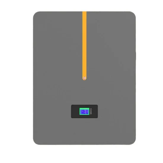
Comparative study on the advantages of hydrogen solar container
This study compares two primary solar energy storage systems—battery and hydrogen storage—in terms of efficiency, cost, and applicability. Battery storage, commonly used in residential solar setups, provides immediate energy with a high round-trip efficiency.. This review explores the advancements in solar technologies, encompassing production methods, storage systems, and their integration with renewable energy solutions. It examines the primary hydrogen production approaches, including thermochemical, photochemical, and biological methods.. effective storage solutions. This study compares two primary solar energy storage systems—battery and hydrogen storage—in terms of efficie cy, cost, and applicability. Battery storage, commonly used in residential solar setups, provides immediate energy with high round-trip efficiency. In. . Hydrogen storage is a compelling motivation in the realm of energy storage due to its unique advantages and potential. As an emerging storage technology, hydrogen offers a flexible and scalable solution for storing renewable energy over extended periods, addressing the intermittency challenge of. . This study presents an optimisation study of sizing and operational strategy parameters of a grid -connected photovoltaic (PV)-hydrogen/battery systems using a Multi-Objective Modified Firefly Algorithm (MOMFA). An operational strategy that the ability utilisesof hydrogen to store energy over a. . This study compares two primary solar energy storage systems—battery and hydrogen storage—in terms of efficiency, cost, and applicability. Battery storage, commonly used in residential solar setups, provides immediate energy with a high round-trip efficiency. In contrast, hydrogen storage, though. . This study investigates and compares the economic analysis of renewable energy-based systems incorporating photovoltaic (PV) panels, electrolyzer, fuel cell (FC), and a hydrogen tank for single houses in North America. Three systems consisting of PV/battery bank, PV/hydrogen, and PV/battery.
Read More
What are the application scenarios of inductor solar container
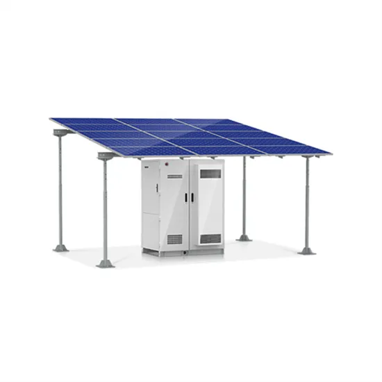
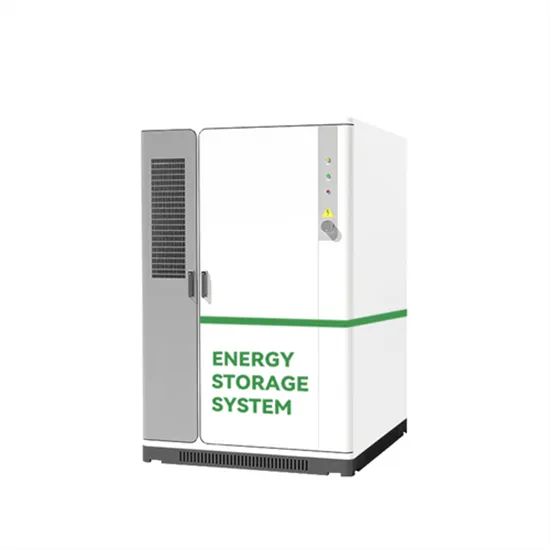
These containers are revolutionizing the way solar energy is deployed, particularly in remote areas, disaster relief zones, military operations, construction sites, and temporary industrial setups.. Power inductor specifications typically include inductance value (mH),rated current (A),saturation current (A),and DCR (mO)as the main parameters. Inductors,as key components in electronic circuits,can be classified into various types based on structure,manufacturing process,and application. . So, in recent years, there has a trend in solar inverter system to use in-package hall-effect current sensor to replace the traditional thorough-hole one, that benefits solar system performance, power efficiency and reliability. This application note summarizes common solar application scenarios. . ic circuits, to keep them a parallel with a resistor (R) and ca acitor (C). "L" is used as the inductor symbol. Th fs with the magnetic properties for his design. These properties are: saturation Bs, permeabi is often misunderstood and can be troublesome. This article will address how inductors. . As installations exceed hundreds of megawatts, EPC contractors face growing challenges around power conditioning, grid code compliance, and equipment durability. Electrical infrastructure within these plants must manage high currents, variable irradiance, and rapidly fluctuating grid demands — all. . These containers are revolutionizing the way solar energy is deployed, particularly in remote areas, disaster relief zones, military operations, construction sites, and temporary industrial setups. This article explores the benefits, features, components, and industrial applications of solar power. . Whether it is a limited energy supply, lack of foundation, strict time management or limited liquidity - our Solarcontainer always offers the right solution! Agriculture and watermanagment Additional solar power supply for self-consumption to support existing generators. Remote charging stations.
Read More
What type of solar container component is inductor
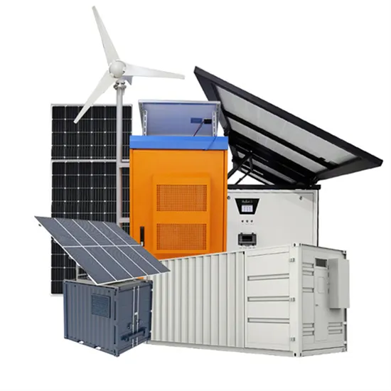
Inductors are key components that make up inverters, and their performance has a significant impact on the overall efficiency, stability, and electromagnetic compatibility of the system. If divided according to the manufacturing process, the most common types of SMD inductors are. . Air Core Inductors Air core inductors are the simplest type, consisting of a coil of wire with no core material. The coil itself is the inductor, . Types of Power Inductors Power inductors used for buck converters are roughly classified into three types. The wire wound ferrite type is further. . Power inductor specifications typically include inductance value (mH),rated current (A),saturation current (A),and DCR (mO)as the main parameters. Inductors,as key components in electronic circuits,can be classified into various types based on structure,manufacturing process,and application. . The core principle behind a color ring inductor is electromagnetic induction. When an unstable current flows through the inductor, it creates a changing magnetic field that, in turn, influences the current. This property, known as " self-inductance," helps the inductor oppose rapid changes in. . A solar inverter (also called a photovoltaic or PV inverter) converts direct current (DC) into alternating current (AC) and is widely used in solar photovoltaic power generation systems. Solar inverters available today are generally divided into three types: central inverters, string inverters and. . Solar power systems convert sunlight into electricity using photovoltaic cells. The generated electricity is in direct current (DC) form, which needs to be converted into alternating current (AC) for use in homes and businesses. This is where inductive components come in. Inverters, which convert. . From portable units to large-scale structures, these self-contained systems offer customizable solutions for generating and storing solar power. In this guide, we'll explore the components, working principle, advantages, applications, and future trends of solar energy containers. Photovoltaic.
Read More
Inductor solar container power formula
The equation for energy stored in an inductor is given by: WL = (1/2) * L * I2 Where: This equation tells us that the energy stored in the inductor is directly proportional to the square of the current passing through it and the inductance of the coil.. The current across an inductor is equal to the integral of the voltage across the inductor multiplied by the inverse of the inductance plus whatever initial current there was flowing across the inductor. If there was no initial current flowing through the inductor, then I 0 is equal to 0. [pdf]. . As the photovoltaic (PV) industry continues to evolve, advancements in Capacitor and inductor solar container calculation formula have become critical to optimizing the utilization of renewable energy sources. From innovative battery technologies to intelligent energy management systems, these. . The core principle behind a color ring inductor is electromagnetic induction. When an unstable current flows through the inductor, it creates a changing magnetic field that, in turn, influences the current. This property, known as " self-inductance," helps the inductor oppose rapid changes in. . The following formulas and equations can be used to calculate the inductance and related quantities of different shapes of inductors as follow. The inductance of the inductor from the basic formula of inductor: Where Di/dt is the instantaneous rate of current change through the inductor. ito =. . This example demonstrates the application of the inductor energy storage equation in calculating the energy stored in an inductor''s magnetic field for a given inductance Energy Stored in Coil #1Energy Stored in Coil #2Total Energy in Coils When I_1 and I_2 Have Reached Constant ValuesSign. . The energy of a capacitor is stored within the electric field between two conducting plates while the energy of an inductor is stored within the magnetic field of a conducting coil. Both elements can be charged (i.e., the stored energy is increased) or discharged (i.e., the stored energy is.
Read More
Power supply solar container inductor is replaced by sendust
Sendust Core, which is made from 6%Al,9%Si and 85%Fe,is mainly used to replace iron powder core because its core loss is80%less than powdered iron, so it can be applied with the frequency above 8kHz.Sendust core has a saturation flux density of1.05T and permeability from 14 to 125.The. . This application guide presents some general guidelines for the optimum choice of powder core materials ( MPP, Sendust, Kool Mu®, High Flux or Iron Powder ) for different inductor, choke and filter design requirements. The choice of one type of material over another often depends on the following:. . Sendust Core, which is made from 6%Al,9%Si and 85%Fe,is mainly used to replace iron powder core because its core loss is80%less than powdered iron, so it can be applied with the frequency above 8kHz.Sendust core has a saturation flux density of1.05T and permeability from 14 to 125.The nearly zero. . Magnetics ® is a manufacturer of high quality powder core materials including Kool Mu ® (sendust), Kool Mµ ® MAX, Kool Mu ® Hƒ, Kool Mµ ® Ultra, XFlux ®, XFlux ® Ultra, MPP (molypermalloy), Edge ®, and High Flux. Magnetics powder cores are distributed air gap cores primarily used in power inductor. . High-frequency inductors are essential components in solar inverters, offering superior performance at high frequencies and elevated temperatures, crucial for efficient solar power conversion.. Which are mainly used for inductors and transformers requiring low losses and inductance stability under high DC bias conditions. Production management under strict control of raw materials (nickel, iron, molybdenum, aluminium, and silicon) assures guaranteed consistent quality. Note: All image. . Enter Sendust Cores a revolutionary material designed to outperform traditional iron powder cores while minimizing energy losses. With near-zero magnetostriction, Sendust Cores significantly reduce audible noise in filter inductors, making them the go-to choice for high-performance power conversion.
Read More
Power factor correction solar container inductor
Passive Power Factor Correction involves using passive elements like capacitors and inductors to offset the inductive effects of the load. Advantages: Simple and low-cost solution. Suitable for constant loads. Disadvantages: Less effective for variable loads.. Power Factor Correction (PFC) is a critical concept in the realm of electrical systems, aimed at improving power efficiency and minimizing energy losses. Power factor, defined as the ratio of real power to apparent power, reflects how effectively electrical power is being utilized. A lower power. . Power factor correction (PFC) is an essential aspect of grid-tied solar PV systems to ensure efficient power distribution and energy management. In a solar system, poor power factor can result in higher reactive power consumption, increased energy losses, and potential penalties from grid. . Power Factor Correction (PFC) is a technique used to align the electrical current drawn by a load more closely with the electrical power’s voltage wave. By reducing the angle between these two waves, the power factor becomes closer to a perfect value of 1, thereby making the electrical system more. . MPS Industries is a leading provider of power factor correction (PFC) inductors. Our PFC inductors are designed to improve the power factor of a system by storing and releasing energy. This results in more efficient utilization of the electrical grid, lower energy costs, and a longer equipment. . A power factor correction (PFC) circuit intentionally shapes the input current to be in phase with the instantaneous line voltage and minimizes the total apparent power consumed. While this is advantageous to utility companies, a PFC circuit also provides benefits in end applications. This topic. . The power factor of an inductive load is corrected (improved) by placing a capacitor (often called a "shunt capacitor") in parallel with the load. The change in properties to the circuit (due to the capacitor) are represented in the following phasor diagram: We see that the "improved" circuit has a.
Read More