IRONRIDGE JAYBOX RAIL MOUNTED PRICED AS EACH
Urban rail ground hybrid solar container device
s is feasibleto enhance urban sustainability. Solar-powered metro rail systems provide a sustainable alternative to conventional grid-powered transit by decreasing dependence on fossil fuels,lowering carbon solar ower & storage in met. s is feasibleto enhance urban sustainability. Solar-powered metro rail systems provide a sustainable alternative to conventional grid-powered transit by decreasing dependence on fossil fuels,lowering carbon solar ower & storage in met olar power and storage in metro rail systems. Hybrid grid. . With the increasing energy consumption of urban rail transportation, the on-board hybrid energy storage system, which integrates various energy storage technologies, can effectively recycle the regenerative braking energy. It not only solves the problems of voltage increase, temperature rise, and. . Energy management is an important link in the effective functioning of hybrid energy storage systems (HESS) within urban rail trains. This factor significantly impacts the operational stability and economic efficiency of urban rail systems. Safety issues arise from DC bus voltage fluctuations due. . We’re excited to spotlight a recent deployment between Makinex Renewables and Degnan that’s transforming how urban construction sites are powered—starting with the Unanderra Rail Infrastructure Project. Degnan’s Unanderra Station Upgrade, part of Transport for NSW’s Transport Access Program. . There are three major challengesto the broad implementation of energy storage systems (ESSs) in urban rail transit: maximizing the absorption of regenerative braking power,enabling online global optimal control,and ensuring algorithm portability. What are the challenges faced by hybrid energy. . For urban metro rail systems, the designs can be integrated with solar panel installation options on station rooftops or existing rail tracks, allowing for the With the world moving increasingly towards renewable energy, Solar Photovoltaic Container Systems are an efficient and scalable means of.
Read More
Rail transit solar container liquid cooling pipeline
The structure of the indirect liquid cooling pipe is illustrated in Fig. 2, consisting of a copper cooling pipe, cooling fins, and a condensing fan.The total dimensions of the cooling pipe are 600 mm in length, 300 mm in height, and 15 mm in width. The number. . performance for battery energy storage systems. To address these issues, a novel two-phase liquid cooling system was developed for containerized battery energy storage systems and f containerized battery energy storage systems. To better assess the system's availability and meet actual application. . gy storage technology is increasingly prominent. The liquid-cooled ESS container system,with its efficient temperature control and outstanding performance,has become a cruc al component of modern energy storage solut er densities,achieving greater energy de -ion batteries for the container storage. . Major projects now deploy clusters of 20+ containers creating storage farms with 100+MWh capacity at costs below $280/kWh. Technological advancements are dramatically improving solar storage container performance while reducing costs. Next-generation thermal management systems maintain optimal. . The structure of the indirect liquid cooling pipe is illustrated in Fig. 2, consisting of a copper cooling pipe, cooling fins, and a condensing fan.The total dimensions of the cooling pipe are 600 mm in length, 300 mm in height, and 15 mm in width. The number of cooling . Today, hydrogen is. . Zero loss in DC parallel connection; reducing station heat management electricity usage by over 30%; liquid cooling heat management ensures battery longevity cycles, reducing LCOS by 20%, and increasing pure profit lifespan by over 3 years; large-capacity energy storage demand for single units. . Immersion liquid cooling technology is an efficient method for managing heat in energy storage systems, improving performance, reliability, and space efficiency. The 5MWh liquid-cooling energy storage system comprises cells, BMS, a 20''GP container, thermal management system, firefighting system.
Read More
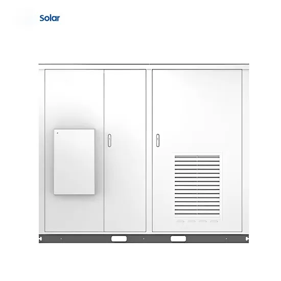
High voltage direct mounted cascade solar container
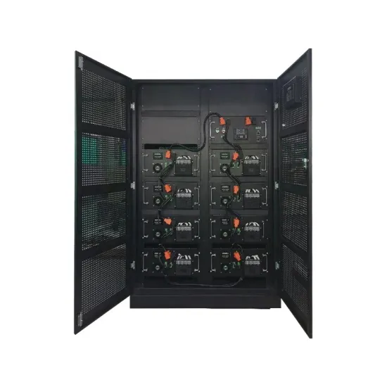
The high-voltage cascade energy storage device has a high protection level of IP54, which adapts to various complex environments and shows excellent adaptability. Its integrated design and direct hanging installation make installation and maintenance simple and convenient.. Major projects now deploy clusters of 20+ containers creating storage farms with 100+MWh capacity at costs below $280/kWh. Technological advancements are dramatically improving solar storage container performance while reducing costs. Next-generation thermal management systems maintain optimal. . The product adopts advanced cascade topology structure, which is composed of incoming reactor, cascade power unit, lithium battery module and precise control and protection equipment, realizing the optimal utilization and storage of energy. The high-voltage cascade energy storage device has a high. . The utility model discloses a high-voltage direct-hanging type cascade energy storage unit which comprises an inversion unit and an expansion unit, wherein the inversion unit comprises an inversion unit shell, an IGBT radiator assembly, an axial flow fan, a film capacitor, a unit control board. . This net-structured high-voltage cascade directly hangs energy storage system stores electric energy through dry battery module, through the charge-discharge process of power unit control to directly link to each other with high-voltage power network, realize the effective. This net-structured. . od solution for high-power applications[6,7 ]. There are three main ways that energy storage devices can be integrated into the CHB sub-modules: direct parallel,paralleled through non-isolated DC-DC converters an id-connected charging and discharging process. For the charging process,in the. . The high-voltage direct-mounted energy storage completely adopts the cascading topology of high-voltage SVG, canceling the booster transformer, and the batteries are dispersed in dozens of PCS unit modules, running independently of each other, and the coupling degree is low. The thermal standby.
Read More