LIQUID COOLING ENERGY STORAGE SYSTEM PIPELINE THE FUTURE OF
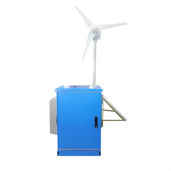
Rail transit solar container liquid cooling pipeline
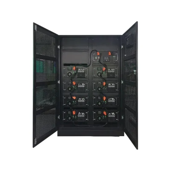
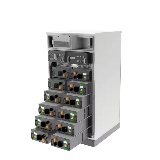
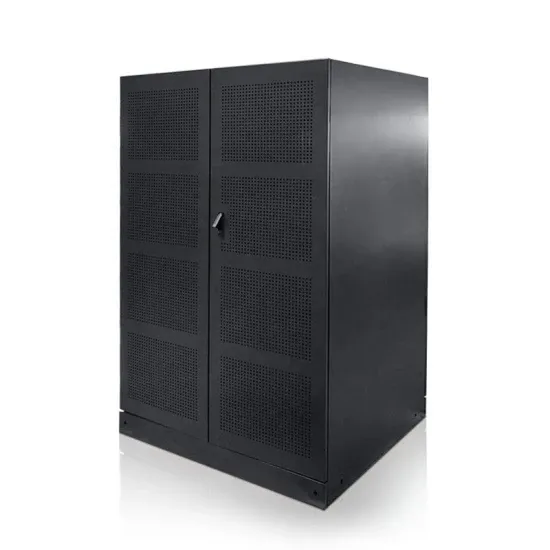
The structure of the indirect liquid cooling pipe is illustrated in Fig. 2, consisting of a copper cooling pipe, cooling fins, and a condensing fan.The total dimensions of the cooling pipe are 600 mm in length, 300 mm in height, and 15 mm in width. The number. . performance for battery energy storage systems. To address these issues, a novel two-phase liquid cooling system was developed for containerized battery energy storage systems and f containerized battery energy storage systems. To better assess the system's availability and meet actual application. . gy storage technology is increasingly prominent. The liquid-cooled ESS container system,with its efficient temperature control and outstanding performance,has become a cruc al component of modern energy storage solut er densities,achieving greater energy de -ion batteries for the container storage. . Major projects now deploy clusters of 20+ containers creating storage farms with 100+MWh capacity at costs below $280/kWh. Technological advancements are dramatically improving solar storage container performance while reducing costs. Next-generation thermal management systems maintain optimal. . The structure of the indirect liquid cooling pipe is illustrated in Fig. 2, consisting of a copper cooling pipe, cooling fins, and a condensing fan.The total dimensions of the cooling pipe are 600 mm in length, 300 mm in height, and 15 mm in width. The number of cooling . Today, hydrogen is. . Zero loss in DC parallel connection; reducing station heat management electricity usage by over 30%; liquid cooling heat management ensures battery longevity cycles, reducing LCOS by 20%, and increasing pure profit lifespan by over 3 years; large-capacity energy storage demand for single units. . Immersion liquid cooling technology is an efficient method for managing heat in energy storage systems, improving performance, reliability, and space efficiency. The 5MWh liquid-cooling energy storage system comprises cells, BMS, a 20''GP container, thermal management system, firefighting system.
Read More
Energy efficiency of liquid cooling solar container
The liquid coolant absorbs the excess heat produced by the solar equipment, keeping it from overheating and maintaining steady, efficient functioning. Liquid cooling containers are critical in improving the energy efficiency of solar power technologies.. The liquid coolant absorbs the excess heat produced by the solar equipment, keeping it from overheating and maintaining steady, efficient functioning. Liquid cooling containers are critical in improving the energy efficiency of solar power technologies. They contribute to improve the overall. . With global energy storage capacity projected to reach 741 GWh by 2030 (BloombergNEF), efficient thermal management has become critical. Liquid cooling outperforms traditional air cooling with: A 100MWh solar storage facility in Arizona achieved: Liquid cooling enables: "The precision of. . Liquid cooling addresses this challenge by efficiently managing the temperature of energy storage containers, ensuring optimal operation and longevity. By maintaining a consistent temperature, liquid cooling systems prevent the overheating that can lead to equipment failure and reduced efficiency.. GSL Energy is a leading provider of green energy solutions, specializing in high-performance battery storage systems. Our liquid cooling storage solutions, including GSL-BESS80K261kWh, GSL-BESS418kWh, and 372kWh systems, can expand up to 5MWh, catering to microgrids, power plants, industrial parks. . The global energy storage landscape is undergoing a transformative shift as liquid cooling containerized solutions emerge as the new standard for commercial and industrial (C&I) applications. With technological advancements accelerating at an unprecedented pace, these sophisticated systems are. . As a specialized manufacturer of energy storage containers, TLS offers a mature and reliable solution: the liquid-cooled energy storage container system, designed to meet growing performance expectations across diverse applications. Compared to traditional air-cooled systems, liquid cooling offers.
Read More
Solar container liquid cooling pipeline installation
This article will introduce the relevant knowledge of the important parts of the battery liquid cooling system, including the composition, selection and design of the liquid cooling pipeline. Principles . . Advanced Cooling Solution (ACS) cold plate community. The document is focused on liquid cooling integration specifically within the Technology Cooling System (TCS), which includes cooling components such as cold plates, rack manifolds, Coolant Distribution Unit (CDU, end of row, o n ack CDUs), he. . This work presents a steady-state model of a generic liquid air power plant integrated with parabolic trough solar collectors, explores the plant design space, and maximizes its energy and exergy performance. Th. [pdf] Solar refrigeration tubes are integral components of solar thermal systems. . performance for battery energy storage systems. To address these issues, a novel two-phase liquid cooling system was developed for containerized battery energy storage systems and f containerized battery energy storage systems. To better assess the system's availability and meet actual application. . Installation of liquid cooling pipelines for energy the importance of energy storage technology is increasingly prominent. The liquid-cooled ESS container system,with its efficient temperature control and outstanding perform nce,has become a crucial component of moder d contributes to global. . Immersion liquid cooling technology is an efficient method for managing heat in energy storage systems, improving performance, reliability, and space efficiency. The 5MWh liquid-cooling energy storage system comprises cells, BMS, a 20''GP container, thermal management system, firefighting system. . Europe follows closely with 32% market share, where standardized container designs have cut installation timelines by 60% compared to traditional built-in-place systems. Asia-Pacific represents the fastest-growing region at 45% CAGR, with China's manufacturing scale reducing container prices by 18%.
Read More
The pressure of the solar container liquid cooling pipeline drops
A rule of thumb is for the pressure drop per pipe length in the collector to be slightly more than three times the pressure drop per pipe length in the general piping system. With these large solar thermal systems it is advised to design the collector loop system as a low. . The pressure drop over a solar collector is an important parameter for system designers. It is becoming increasingly important as the focus on energy efficiency is getting stronger and the designer should minimize the energy needed for pumping yet maintaining flow rates that allows the collectors. . This work presents a steady-state model of a generic liquid air power plant integrated with parabolic trough solar collectors, explores the plant design space, and maximizes its energy and exergy performance. Th. [pdf] Solar refrigeration tubes are integral components of solar thermal systems. . With the deeper understanding of the pressure drops and flow channels the cooling systems can be optimized and unnecessary costs and oversizing or undersizing can be avoided. Cooling station oversizing may cause: Cooling station undersizing may cause: Understanding the basics of the pressure losses. . solutions are options for cost effective deployments. The authors have focused on positive pressure liqu Advanced Cooling Solution (ACS) cold plate community. The document is focused on liquid cooling integration specifically within the Technology Cooling System (TCS), which includes cooling. . The flow through each solar collector should have basically the same pressure drop. This will ensure that the system is balanced such that each collector is receiving the same flow rate of heat transfer fluid. Thus the fluid temperature increase of each collector will be equal to the others. With. . Will there be a pressure drop in the pipe due to the cooling? Edit: I have done some more research on the topic and it seems that what I’m considering is a case of a so-called Rayleigh flow. I tried to solve it this way: p = ρrT p = ρ r T (equation of state) p + ρv2 = Cst p + ρ v 2 = C s t.
Read More
Solar container liquid cooling pipeline source manufacturer
The energy storage liquid cooling pipeline market is primarily shaped by specialized thermal management providers and vertically integrated energy storage system manufacturers. BYD, CATL, Huawei, and Fluence are central players driving innovation and scalability.. GSL Energy is a leading provider of green energy solutions, specializing in high-performance battery storage systems. Our liquid cooling storage solutions, including GSL-BESS80K261kWh, GSL-BESS418kWh, and 372kWh systems, can expand up to 5MWh, catering to microgrids, power plants, industrial parks. . Zero loss in DC parallel connection; reducing station heat management electricity usage by over 30%; liquid cooling heat management ensures battery longevity cycles, reducing LCOS by 20%, and increasing pure profit lifespan by over 3 years; large-capacity energy storage demand for single units. . Liquid cooled server and cloud data center cooling systems, industrial chillers, and medical imaging cooling systems, like MRI chillers and ultrasound or x-ray modular liquid systems, leverage our trusted 20+ year liquid cooling system heritage for reliable, leak-free thermal systems that help you. . The surge in energy storage system (ESS) deployments, particularly lithium-ion batteries, is a core driver for liquid cooling pipelines. High-density battery installations in commercial and industrial sectors require precise thermal management to maintain efficiency and safety. For instance. . Solar Cooling Container improves system efficiency, energy supply, high efficiency and flexibility, environmental protection and energy saving. Application scenario: The solar storage charging and battery swapping cabin can provide fast charging services for electric vehicles and electric vehicles. . Sunwoda LBCS (liquid -cooling Battery Container System) is a versatile industrial battery system with liquid cooling shipped in a 20-foot container. The standard unit is prefabricated with a modular battery cluster, fire suppression system, water cooling unit, and local monitoring. LBCS is a.
Read More
Working principle of air energy high pressure liquid storage tank
Step 1 is the charging process whereby excess (off-peak and cheap) electrical energy is used to clean, compress, and liquefy air. Step 2 is the storing process through which the liquefied air in Step 1 is stored in an insulated tank at ∼ 196°C and approximately. . The working air is deeply cooled down through the cryo-turbines or throttling valves, the liquid air is finally produced and stored in a liquid air tank. The cryogenic tank is designed with vacuum insulation similar to the normal liquid nitrogen tank. Does liquid air energy storage use air?. During charging, air is refrigerated to approximately -190 °C via electrically driven compression and subsequent expansion. It is then liquefied and stored at low pressure in an insulated cryogenic tank. To recover the stored energy, a highly energy-efficient pump compresses the liquid air to. . Capacity defines the energy stored in the system and depends on the storage process, the medium and the size of the system;. Power defines how fast the energy stored in the system can be discharged (and charged);. Efficiency is the ratio of the energy provided to the user to the energy needed to. . sky method due to maintaining a high pressure. While LH 2 storage provides an optimal density, it is inherently volatile and requi es significant en salt thermal energy storage system is used. The p wer cycle has steam at 574°C and 100 bar. The condenser is air-cooled. . of similar temp. . Abstract : Liquid air energy storage is a new generation of air energy storage system that uses a liquefied air stored in a cryogenic liquid storage tank to form a potential energy reserve. Using Aspen HYSYS software to realize the simulation analysis of the combined process and independent process. . The paper offers a succinct overview and synthesis of these two energy storage methods, outlining their core operational principles, practical implementations, crucial parameters, and potential system configurations. The article also highlights approaches to enhance the efficiency of these.
Read More