ONLINE ELECTRICAL SWITCH BOX SHOPPING STORE IN KAZAKHSTAN
Is the failure of electrical equipment to store energy a non-electrical quantity signal
Intermittent - This failure is the partial electronic part breakdown of an ESDS item and generally causes the item to give low output or other erroneous signals. Catastrophic - This failure is the total failure of electronic parts, assemblies, and equipment caused. . 1.1.2 2/8 Electrical charge (static electricity) is the quantity of electricity, negative or positive, held by an object at rest and construed as an excess or deficiency of _________. Don't know? 1.1.1 1/3 ESD must be applied to prevent equipment damage during installation, ________, and repair.. Aiming at the problem of low reliability of electric power equipment failure rate analyzed by using the data of statistical equipment, this paper puts forward health index, which is according to the actual operation status, the evaluation and maintenance of the equipment, to reflect the operation. . Each piece of electrical equipment on a distribution system has a probability of failing. When first installed, a piece of equipment can fail due to poor manufacturing, damage during shipping, or improper installation. Healthy equipment can fail due to extreme currents, extreme voltages. . Around the globe energy storage systems are being installed at an unprecedented rate, and for good reasons. There are a lot of benefits that energy storage systems (ESS) can provide, but along with those benefits come some hazards that need to be considered. This blog will talk about a handful of. . A statistical model that outlines the expectant rate of a computer to fail at three central stages of its life cycle. 1. Early failure. 2. Random failure. 3. Wear-out failure. When a computer fails relatively close to the beginning of their life cycle. - Failure rate decreases rapidly from high to. . An electrical fault occurs when a system or piece of equipment departs from its normal operating state, resulting in abnormal current flow. This can result in overheating, equipment damage, or safety risks. Protective devices isolate faults to preserve safety and reliability. What is an Electrical.
Read More
Switch solar container electrical equipment action
This comprehensive guide covers everything professional installers need to know about solar disconnect switches: NEC requirements, disconnect types and applications, technical specifications, proper sizing methods, installation location rules, step-by-step installation procedures. . Among the most important components in any renewable energy installation is the isolator switch—a device that can literally be the difference between a safe working environment and a potentially dangerous situation. Whether you’re a solar installer, facility manager, or property owner with. . Disconnect switches are often overlooked in the planning and installation of commercial PV systems—until they result in cost overruns, code compliance issues, or safety hazards. During a recent roundtable of Pure Power's senior project managers with decades of solar + storage engineering. . Smart Integration is Standard: Modern solar disconnect switches increasingly feature IoT connectivity and remote monitoring capabilities, enabling predictive maintenance and automated emergency response – a critical advancement as solar installations scale beyond 150GW in the US market. Oversizing. . A solar disconnect switch is a critical safety device required in every photovoltaic system to protect installers, maintenance workers, and first responders. Under NEC Article 690.13, all solar installations must include readily accessible disconnect means that allow complete isolation of the. . A solar disconnect switch is a safety device required by the National Electrical Code (NEC Article 690.13) that allows users to safely shut off power flow in photovoltaic systems. These switches protect people and equipment by interrupting electricity between solar panels, inverters, and batteries. . Shipping containers are often used as remote offices, workshops or data shelters on construction sites, farms, and emergency zones. When the grid is hundreds of feet away (or non-existent), a self-contained power solution is ideal. For instance, specialized units like the LZY-MSC1 Sliding Mobile.
Read More
Gis switch abb solar container mechanism cannot store energy
Faulty Energy Storage Limit Switch (S1) The S1 limit switch in the VD4-12 controls motor start/stop and signal circuits. [pdf] Inspect the Mechanism: Remove the switch from the panel and check for any physical obstructions within the mechanism. Use compressed air to remove any dust or. . ABB’s medium voltage switchgear (1 kV to 52 kV according to the IEC standards) are designed to connect and protect an evolving grid. Depending on the insulation medium that protect the energized components in the medium voltage switchgear, both primary and secondary medium voltage switchgear can be. . Check if power is reaching the terminal block in the switchgear and confirm that the control power switch 2ZK in the storage circuit is in the closed position. 2. Faulty Energy Storage Limit Switch (S1) The S1 limit switch in the VD4-12 controls motor start/stop and signal circuits. [pdf] Inspect. . As the photovoltaic (PV) industry continues to evolve, advancements in Abb cannot store energy have become critical to optimizing the utilization of renewable energy sources. From innovative battery technologies to intelligent energy management systems, these solutions are transforming the way we. . switch to be monitored during filling. Full details are included with the filling adaptor. SafeLink units must be stored under c ver in a dry and well-ventilated area. SafeLink units are shipped from the factory filled w th SF6 gas and ready for installat de a very compact switchgear solution.. Abb knife switch equipment container mech ns that achieve extensive quality that stores energy for use at a later time to maximize system efficiency. The different versions of the pre-engineered and industrialized ESM allow scalability, reduction of installation costs, high reliability and re. . Gas-insulated switchgear (GIS) is a compact, robust, low-maintenance medium voltage solution that enhances the reliability and sustainability of the power grid, making it ideal for the future of the utility industry. Its ability to handle medium voltage, provide phase-to-phase isolation and.
Read More
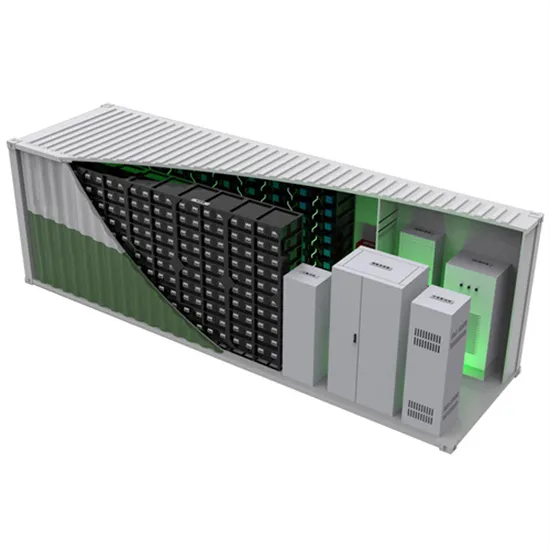
The universal solar container switch cannot automatically store energy
The biggest problem caused by the lack of a zero line is that the voltage signal cannot be directly obtained, and thus the electric energy cannot be calculated. This is the core reason why the existing smart single-fire light control switches on the market cannot measure electric. . At the heart of this issue lies the PC switch – those unassuming components in power converters that can't store excess energy. Recent data from the 2025 Gartner Energy Storage Report shows 68% of renewable energy systems experience 12-18% efficiency drops due to this limitation. The energy storage. . As the photovoltaic (PV) industry continues to evolve, advancements in How to automatically store energy on the solar container switch have become critical to optimizing the utilization of renewable energy sources. From innovative battery technologies to intelligent energy management systems, these. . An interlock system allows the switch to be opened (off) by the producer, but cannot be closed (on) until reset by All disconnect devices must have locking provisions that accept a PG&E padlock with a 5/16-inch lock shaft. Keyed locks are not allowed. An interlock system allows the switch to be. . At night, when solar energy is unavailable, the stored electricity is automatically discharged from the energy storage container to the distribution box. This ensures an uninterrupted power supply. The grid also allows generators to be located closer to resources (e.g., fuel supply, water. . During off-peak time, the PCS takes the energy from the grid to store in the BESS. In essence, the PCS's main function is to convert the power between the energy storage system and the grid, and vice versa. It accomplishes that by offering a bi-directional flow from DC-AC and AC-DC. [pdf] What is a. . The universal energy storage switch delivers power through an innovative mechanism that enables efficient energy management and distribution. 1. The switch optimizes energy flow to meet demand and supply, 2. It employs sophisticated technology for seamless conversion and management, 3. Integration.
Read More

How to store energy in gis switch
Photo source from SIEMENS Energy company website This section deals with the actual operation of gas-insulated switchgear (GIS). The operation is best illustrated by using an example switching scenario as follows. In this example, the portion of the Koch substation shown is. . how does gis switch store energy. Work with Mi rosoft Excel files in ArcGIS Pro. You add Excel files to a project in the same way as other data: click the Add convenient storage and transport. Gas handling systems with filters, compressors, and t recommended on a completed GIS. However, it may be. . Explore how energy storage GIS solutions enhance planning and efficiency in sustainable energy systems. Energy storage GIS solutions integrate Geographic Information Systems with energy retention technologies to enhance the planning, operation, and management of power systems, particularly as the. . GE Vernova provides a full range of SF₆ as well as SF₆-free g³ gas-insulated substations (GIS) from 72.5 kV up to 800 kV for utilities and industries worldwide, including hybrid configurations. GE Vernova’s Gas-Insulated Lines (GIL) Dual Gas, available with SF₆ or SF₆-free with g³ gas, meet the. . Gas-insulated switchgear helps fix these problems. It helps keep the power flow steady and the distribution reliable. This makes it an important part of the electrical infrastructure that is ready for the future. Wind and solar electricity are not always reliable. The weather and the time of day. . GIS is applied across the solar energy business, from mapping energy potential to using commercial analytics and engaging with stakeholders. Geothermal energy Important GIS-supported workflows include determining prime locations to implement geothermal technologies, finding potential markets, and. . Gas-Insulated Switchgear (GIS) uses SF₆ gas inside sealed metal enclosures to enable compact, high-voltage, reliable power switching — ideal for urban/substation use. Gas-Insulated Switchgear (GIS) is a compact power distribution system where all electrical parts are enclosed in a metal housing.
Read More
How to store energy in a three-position switch
After charging the spring energy store, . One type of rocker switch is the 3-position rocker switch, which has three positions: On, Off, and On with light. In this article, we will discuss the wiring diagram for a 3-position rocker switch. . . The switch typically has three connection points: Depending on the position, the switch can direct power from either Line 1 or Line 2 to the connected load. This setup is beneficial for systems with single-phase inverters but can also accommodate more complex configurations like three-phase. . The 3 Position Switch is a versatile electromechanical component designed to connect a single input to one of three different outputs or circuits. This switch is commonly used in applications requiring multiple operational modes, such as selecting between power sources, controlling motor speeds, or. . A 3 position switch usually consists of a lever or knob that can be moved into three different positions: Up, Middle, and Down. Each position has a specific function and controls a different part of the circuit. The switch diagram typically shows the various terminals and labels, allowing the user. . A three position switch is a type of electrical switch that has three different positions or settings. It is commonly used to control the flow of electricity or to switch between different circuits or functions. The three position switch diagram provides a visual representation of how the switch. . A 3 position switch is a commonly used electrical component that allows you to control the flow of electricity between multiple circuits or devices. It has three different positions – commonly referred to as “up”, “center”, and “down” – and each position corresponds to a specific circuit. . The wiring of a 3 position toggle switch is fairly straightforward, and understanding how to properly wire one can be an essential skill for anyone working with electrical systems. One of the main features of a 3 position toggle switch is its ability to provide three different positions or.
Read More