UNDERSTANDING POWER INDUCTOR PARAMETERS
Power factor correction solar container inductor
Passive Power Factor Correction involves using passive elements like capacitors and inductors to offset the inductive effects of the load. Advantages: Simple and low-cost solution. Suitable for constant loads. Disadvantages: Less effective for variable loads.. Power Factor Correction (PFC) is a critical concept in the realm of electrical systems, aimed at improving power efficiency and minimizing energy losses. Power factor, defined as the ratio of real power to apparent power, reflects how effectively electrical power is being utilized. A lower power. . Power factor correction (PFC) is an essential aspect of grid-tied solar PV systems to ensure efficient power distribution and energy management. In a solar system, poor power factor can result in higher reactive power consumption, increased energy losses, and potential penalties from grid. . Power Factor Correction (PFC) is a technique used to align the electrical current drawn by a load more closely with the electrical power’s voltage wave. By reducing the angle between these two waves, the power factor becomes closer to a perfect value of 1, thereby making the electrical system more. . MPS Industries is a leading provider of power factor correction (PFC) inductors. Our PFC inductors are designed to improve the power factor of a system by storing and releasing energy. This results in more efficient utilization of the electrical grid, lower energy costs, and a longer equipment. . A power factor correction (PFC) circuit intentionally shapes the input current to be in phase with the instantaneous line voltage and minimizes the total apparent power consumed. While this is advantageous to utility companies, a PFC circuit also provides benefits in end applications. This topic. . The power factor of an inductive load is corrected (improved) by placing a capacitor (often called a "shunt capacitor") in parallel with the load. The change in properties to the circuit (due to the capacitor) are represented in the following phasor diagram: We see that the "improved" circuit has a.
Read More
Power supply solar container inductor is replaced by sendust
Sendust Core, which is made from 6%Al,9%Si and 85%Fe,is mainly used to replace iron powder core because its core loss is80%less than powdered iron, so it can be applied with the frequency above 8kHz.Sendust core has a saturation flux density of1.05T and permeability from 14 to 125.The. . This application guide presents some general guidelines for the optimum choice of powder core materials ( MPP, Sendust, Kool Mu®, High Flux or Iron Powder ) for different inductor, choke and filter design requirements. The choice of one type of material over another often depends on the following:. . Sendust Core, which is made from 6%Al,9%Si and 85%Fe,is mainly used to replace iron powder core because its core loss is80%less than powdered iron, so it can be applied with the frequency above 8kHz.Sendust core has a saturation flux density of1.05T and permeability from 14 to 125.The nearly zero. . Magnetics ® is a manufacturer of high quality powder core materials including Kool Mu ® (sendust), Kool Mµ ® MAX, Kool Mu ® Hƒ, Kool Mµ ® Ultra, XFlux ®, XFlux ® Ultra, MPP (molypermalloy), Edge ®, and High Flux. Magnetics powder cores are distributed air gap cores primarily used in power inductor. . High-frequency inductors are essential components in solar inverters, offering superior performance at high frequencies and elevated temperatures, crucial for efficient solar power conversion.. Which are mainly used for inductors and transformers requiring low losses and inductance stability under high DC bias conditions. Production management under strict control of raw materials (nickel, iron, molybdenum, aluminium, and silicon) assures guaranteed consistent quality. Note: All image. . Enter Sendust Cores a revolutionary material designed to outperform traditional iron powder cores while minimizing energy losses. With near-zero magnetostriction, Sendust Cores significantly reduce audible noise in filter inductors, making them the go-to choice for high-performance power conversion.
Read More
High power solar container inductor manufacturers
This section provides an overview for power inductors as well as their applications and principles. Also, please take a look at the list of 42 power inductor manufacturers and their company rankings.. Shinenergy’s high-frequency inductors provide efficient and stable power conversion with superior magnetic materials and innovative winding technology. Whether for PV energy storage or data centers, Shinenergy inductors maintain low loss and reliability under high frequency and high loads to meet. . Sourcing services for inductors. Coils are also available. Consulting, warehousing, and logistics are offered as secondary services. Serves OEM, aerospace, defense, digital infrastructure, medical, railroad, and lighting utility industries. Triad Magnetics is estimated to have 1000+ employees.. This section provides an overview for power inductors as well as their applications and principles. Also, please take a look at the list of 42 power inductor manufacturers and their company rankings. Here are the top-ranked power inductor companies as of January, 2026: 1.Inductor Supply, Inc. . Murata offers a broad lineup of chip inductors that fit diverse requirements such as compact size, large current, etc. across applications ranging from consumer use to automotive applications that require high reliability. We are also productizing inductors with superior mountability thanks to. . Spang Engineered Solutions designs and manufactures a wide range of inductors, from large chokes supporting hundreds of amps at high frequencies to small surface-mount filter inductors. Our deep experience and proprietary design software allow us to rapidly develop optimized solutions, ensuring the. . Being an industry-leading power inductor manufacturer and supplier, Custom Coils specializes in the design and manufacturing of high current inductors to support various challenging applications with high power conversions. Our experts understand clients’ requirements from different industries and.
Read More
Inductor solar container power formula
The equation for energy stored in an inductor is given by: WL = (1/2) * L * I2 Where: This equation tells us that the energy stored in the inductor is directly proportional to the square of the current passing through it and the inductance of the coil.. The current across an inductor is equal to the integral of the voltage across the inductor multiplied by the inverse of the inductance plus whatever initial current there was flowing across the inductor. If there was no initial current flowing through the inductor, then I 0 is equal to 0. [pdf]. . As the photovoltaic (PV) industry continues to evolve, advancements in Capacitor and inductor solar container calculation formula have become critical to optimizing the utilization of renewable energy sources. From innovative battery technologies to intelligent energy management systems, these. . The core principle behind a color ring inductor is electromagnetic induction. When an unstable current flows through the inductor, it creates a changing magnetic field that, in turn, influences the current. This property, known as " self-inductance," helps the inductor oppose rapid changes in. . The following formulas and equations can be used to calculate the inductance and related quantities of different shapes of inductors as follow. The inductance of the inductor from the basic formula of inductor: Where Di/dt is the instantaneous rate of current change through the inductor. ito =. . This example demonstrates the application of the inductor energy storage equation in calculating the energy stored in an inductor''s magnetic field for a given inductance Energy Stored in Coil #1Energy Stored in Coil #2Total Energy in Coils When I_1 and I_2 Have Reached Constant ValuesSign. . The energy of a capacitor is stored within the electric field between two conducting plates while the energy of an inductor is stored within the magnetic field of a conducting coil. Both elements can be charged (i.e., the stored energy is increased) or discharged (i.e., the stored energy is.
Read More
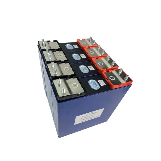
Battery parameters of solar container power station
Battery Bank: LiFePO₄ batteries with 10–100 kWh capacity, 4,000+ cycle life for durability. Inverter & Control System: Hybrid or off-grid inverters with MPPT tracking, remote monitoring, load prioritization, and AC/DC balancing.. We combine high energy density batteries, power conversion and control systems in an upgraded shipping container package. Lithium batteries are CATL brand, whose LFP chemistry packs 1 MWh of energyinto a battery volume of 2.88 m3 weighing 5,960 kg. Our design incorporates safety protection. . ers lay out low-voltage power distribution and conversion for a b de ion – and energy and assets monitoring – for a utility-scale battery energy storage system entation to perform the necessary actions to adapt this reference design for the project requirements. ABB can provide support during all. . The battery cell adopts the lithium iron phosphate battery for energy storage. At an ambient temperature of 25°C, the charge-discharge rate is 0.5P/0.5P, and the cycle life of the cell (number of cycles) ≥ 8000 times. Parameters for 314Ah Cell customized configurations, ease of maintenance, and. . When selecting a mobile solar container—or purchasing one—you might be thinking about portability. Behind every compact package, however, are a set of basic technical parameters: panel power, battery capacity, inverter technology, thermal management, and others. These parameters guarantee. . Discover the critical specifications, popular models, and real-world applications of energy storage container batteries. This guide simplifies technical details while highlighting how these solutions empower industries like renewable energy, grid stabilization, and industrial power management.. ost suitable parameter combination of t odology for battery pack modeling is introduced. This energy storage system (ESS) model was dubbed hanalike after the Hawaiian word for "all together" because it is unifying vario s models proposed and validated in recent years. It comprises an ECM that can.
Read More
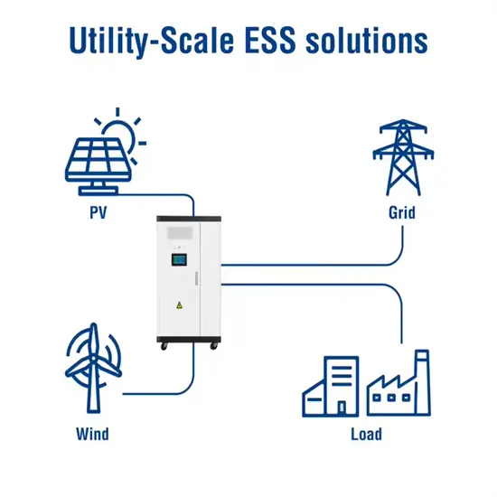
Independent frequency regulation solar container power station project type
In the proposed control scheme, there are five modules: (i) frequency regulation demand assessment, (ii) frequency regulation instruction generation, (iii) wind turbine's virtual inertia control, (iv) energy storage's virtual inertia control, and (v) energy storage's. . The method achieves the cooperative control of wind power and energy storage during frequency regulation, improves the response speed of the wind power system to frequency perturbation, and improves the efficiency of energy storage frequency regulation utilization. Should energy storage and wind. . Key among these are FFR (Fast Frequency Response), FCR-D (Frequency Containment Reserve – Disturbance), FCR-N (Frequency Containment Reserve – Normal), and M-FFR (Moderate Fast Frequency Response). 1. FFR (Fast Frequency Response) FFR is the fastest frequency control service, typically activated. . strategy of PV has been formulated for frequency regul able energy into the power grid at a large scale presents challen able energy penetration increases in power grid, new challenge arises in frequency regulation. Concent utch have different regulating ability and chara and maintains es has. . sponse to random and transient changes in load. Thus, flywheel, SMES, batterie stem's ability to stabilize frequency declines. To address this challenge, Battery Energy Storage Systems (BESS) are now playing a critical role in deliv es challenge to battery life and performance. 10. Conclusion and. . In this study, a method for optimizing The proposed coordinated frequency regulation method can provide bi-directional frequency regulation, effectively addressing the issue of insufficient frequency regulation capability in Energy storage provides an option to mitigate the impact of high PV. . This study proposes a coordinated control strategy for voltage and frequency in a deregulated power system comprising six Generation Companies (GENCOs) and six Distribution Companies (DISCOs). Does load frequency control improve stability and performance in multi-area power systems? This study.
Read More