Rl circuit inductor solar container
HOME / Rl circuit inductor solar container
Let's see what our partners have to say.
PDF Resource Download Center
Access and study high-quality learning materials anytime, anywhere
Introduction
Figure 1 shows a switching circuit that can be used to examine current through an inductor as a function of time. Figure 1. (a) An RL circuit with a switch to turn current on and off. When in position 1, the battery, resistor, and inductor are in series and a current. A resistor–inductor circuit (RL circuit), or RL filter or RL network, is an electric circuit composed of resistors and inductors driven by a voltage or current source. [1]A first-order RL circuit is composed of one resistor and one inductor, either in series driven by a voltage source or in. To understand the current amplitude behavior of RL circuits under applied alternating current voltages. You have studied the behavior of RC circuits under both direct and alternating current conditions. The nal passive component we must consider is the inductor. The voltage across a capacitor is. A circuit with resistance and self-inductance is known as an RL circuit. Figure 14.12 (a) shows an RL circuit consisting of a resistor, an inductor, a constant source of emf, and switches S 1 and S 2 When S 1 is closed, the circuit is equivalent to a single-loop circuit consisting of a resistor and. RL Circuit Definition: An RL circuit is defined as an electrical circuit with a resistor and an inductor connected in series, driven by a voltage or current source. Phasor Diagram: A phasor diagram shows the phase relationships between the voltage and current in the resistor and inductor. An RL circuit, also referred to as a resistor-inductor circuit, plays a foundational role in electrical engineering and inductive elements. In this Article, We will be going through the RL Circuit, We First go through What is the RL Circuit, and We will see RL circuit formulas, Waveforms, and Power. the coils for inductors L1 and L2 respectively, and i1 and i2 are the current through the respective inductors. Φ12 is the flux passing through coil 1 from the magnetic rcuit below, with two inductors L1 and L2, with mutual inductancend part follows by a symmetry argument, with a negated value of.
Rl circuit inductor solar container
10.5: RL Circuits
A circuit with resistance and self-inductance is known as an RL circuit. Figure 10 5 1 a shows an RL circuit consisting of a resistor, an inductor, a constant source of emf, and switches S 1
More
RL Circuit: Theory, Time Constant, and Practical
An RL circuit, also known as a resistor-inductor circuit or RL network, comprises a combination of inductors and resistors and is commonly energized by a power
More
RL Circuits | Physics
Figure 1. (a) An RL circuit with a switch to turn current on and off. When in position 1, the battery, resistor, and inductor are in series and a current is established. In position 2, the battery is removed
More
INDUCTOR CHARGING AND DISCHARGING IN RL CIRCUIT
Solar energy offers the potential to support the battery electric vehicles (BEV) charging station, which promotes sustainability and low carbon emission. In view of the emerging needs of solar energy
More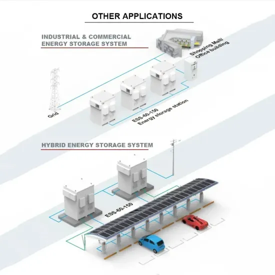
BYJU''S Online learning Programs For K3, K10, K12,
A first-order RL circuit mainly comprises one resistor and one inductor to form an RL circuit. The power factor of this circuit is low because of the inductive load
More
RL Series Circuit | Phasor Diagram | Impedance
The article discusses the characteristics and behavior of RL Series Circuit, which consist of a resistor and inductor connected in series to an AC source. It covers
More
Single Phase Full Wave Controlled Rectifier with RL Load | Power
This video provides a detailed explanation on Single Phase Full Wave controlled rectifier with RL load.#FullwavecontrolledRectifier #RLLoad #PowerElectronics...
More
14.4 RL Circuits – University Physics Volume 2
Figure 14.12 (a) shows an RL circuit consisting of a resistor, an inductor, a constant source of emf, and switches S 1 and S 2 When S 1 is closed, the circuit is
More
Chapter 7 Response of First-order RL and RC Circuits
Section 7.1, 7.2 The Natural Response of RL and RC Circuits Differential equation & solution of a discharging RL circuit Time constant Discharging RC circuit
More
Rl circuits
RL Circuits - Overview In electronics, a resistor–inductor circuit or RL circuit is an electronic circuit consisting of an inductor and a resistor connected in series or in parallel. An RL circuit is a passive
More
RL Circuit
Written by Jiwon Yom Figure 1. RL circuit representation 1 Figure 2. Fluorescent light choke 2 Figure 3. Fluorescent light choke 5 The RL circuit is shown by letter G The RL circuit is one of the simple
More
RL Circuit
The three basic linear circuit elements are the resistor, the capacitor, and the inductor. This lab is concerned with the characteristics of inductors and circuits consisting of a resistor and an inductor in
More
RL Series Circuit Analysis (Phasor Diagram, Examples & Derivation)
An RL circuit (also known as an RL filter or RL network) is defined as an electrical circuit consisting of the passive circuit elements of a resistor (R) and an inductor (L) connected together,
More
RL Circuit
In this Article, we will see the characteristics of circuits consisting of a resistor and an inductor in series (RL circuits). The primary focus will be on the response of an RL circuit to a step
More
Challenge Problems: RL Circuits
RL Circuits Challenge Problems Consider the circuit at left, consisting of a battery (emf an inductor L, resistor R and switch S. ε), For times t<0 the switch is open and there is no current in the circuit. At
More
RL Circuits
The above figure shows a RL series circuit consisting of an inductor of inductance L connected in series with a resistor of resistance R . The switch, S, is closed at a time t = 0 and remains closed.
More
Note 3: Inductors and RL Circuits
Let''s proceed by connecting an inductor to a perfect constant voltage source and explore what insights the equation for the inductor provides us (this is essentially the same situation as when we connect a
More
Step Response of RL and RC Circuits | College of Engineering | USU
This article focuses on the step response of RL and RC circuitsUp to this point, we have analyzed the RL and RC circuits in cases where we suddenly remove the power source from them.
More
RL circuit
A first-order RL circuit is composed of one resistor and one inductor, either in series driven by a voltage source or in parallel driven by a current source. It is one of the simplest analogue infinite impulse
More