RLC RESONANCE ACCEPTOR TANK AMP REJECTOR CIRCUIT
Rlc circuit who is the solar container element
In RLC circuits—those combinations of Resistors (R), Inductors (L), and Capacitors (C)—the real MVPs are the L and C. Let’s break it down: Inductors store energy in magnetic fields. When current flows through their coiled wires, they build up a magnetic charge—sort of like. . An RLC circuit is an electrical circuit consisting of a resistor (R), an inductor (L), and a capacitor (C), connected in series or in parallel. The name of the circuit is derived from the letters that are used to denote the constituent components of this circuit, where the sequence of the. . Just last month, a Texas solar farm reported 12% efficiency gains simply by optimizing their energy storage elements in inverter circuits. Wait, no—it was actually their capacitor-inductor balancing that did the heavy lifting. Renewables aren’t like stable grid power. Solar panels create DC power. . Here in this article, we are going to know the uses, applications, and practical real-life examples of RL, RC, LC, and RLC Circuits. Before going to examples first of all we must know about these circuits. The 'RL' where R indicates the resistance and the L indicates the Inductance, so the RL. . e of the capacitor component. The properties of the parallel RLC circuit can be obtained from t SMES components are depicted. It is primarily made up of three components: a cryogenic refrigerator, a low- and high-temperature superconducting coil magnet, a d helium/nitrogen liquid. . While the. . Series RLC circuits consist of a resistance, a capacitance and an inductance connected in series across an alternating supply Thus far we have seen that the three basic passive components of: Resistance, Inductance, and Capacitance have very different phase relationships to each other when. . ÎThree identical EMF sources are hooked to a single circuit element, a resistor, a capacitor, or an inductor. The current amplitude is then measured as a function of frequency. Which one of the following curves corresponds to an inductive circuit? ÎBelow are shown the driving emf and current vs.
Read More
Measurement of capacitor tank circuit
Working Principle: The principle of capacitive level measurement is based on change of capacitance. An insulated electrode acts as one plate of capacitor and the tank wall (or reference electrode in a non-metallic vessel) acts as the other plate. The capacitance depends on the fluid. . A tank circuit, consisting of an inductor (L) and a capacitor (C) wired in parallel or series is part of electronic circuit fundamentals. Another name used to describe a tank circuit is a resonant circuit. A tank circuit is particularly useful in the design of power supplies, filters, oscillators. . In this post I will talk about 6 easy yet accurate capacitance meter circuits using the ubiquitous IC 555 and many other easily available ICs. Capacitors are one of the main electronic components which come under the passive component family. These are extensively used in electronic circuits and. . Level measurements are broadly classified in two groups: In direct methods, the level is indicated directly by means of simple mechanical devices. The measurement is not affected by changes in material density. Few examples are: In Indirect methods, the level is converted in a measurable signal. . In this hands-on AC electronics experiment, build a parallel resonant inductor-capacitor circuit and learn about oscillation, resonant frequency, and damping. If an inductor and a capacitor are connected in parallel with each other, as illustrated in Figure 1, and then briefly energized by. . As you know, a capacitor has two terminals, and we measure capacitors in terms of capacitance. Capacitance (C) is the ability of a capacitor to store energy. The unit of capacitance is Farad. Let’s see some fundamental mathematics of capacitance. You can see that capacitance is the ratio of total. . Therefore, understanding how capacitance works not only provides insight into the functionality of capacitors but also helps in the analysis and design of electrical circuits. Measuring capacitance accurately is crucial for ensuring the reliability and performance of electronic devices. Various.
Read More
Rl circuit inductor solar container
Figure 1 shows a switching circuit that can be used to examine current through an inductor as a function of time. Figure 1. (a) An RL circuit with a switch to turn current on and off. When in position 1, the battery, resistor, and inductor are in series and a current. . A resistor–inductor circuit (RL circuit), or RL filter or RL network, is an electric circuit composed of resistors and inductors driven by a voltage or current source. [1] A first-order RL circuit is composed of one resistor and one inductor, either in series driven by a voltage source or in. . To understand the current amplitude behavior of RL circuits under applied alternating current voltages. You have studied the behavior of RC circuits under both direct and alternating current conditions. The nal passive component we must consider is the inductor. The voltage across a capacitor is. . A circuit with resistance and self-inductance is known as an RL circuit. Figure 14.12 (a) shows an RL circuit consisting of a resistor, an inductor, a constant source of emf, and switches S 1 and S 2 When S 1 is closed, the circuit is equivalent to a single-loop circuit consisting of a resistor and. . RL Circuit Definition: An RL circuit is defined as an electrical circuit with a resistor and an inductor connected in series, driven by a voltage or current source. Phasor Diagram: A phasor diagram shows the phase relationships between the voltage and current in the resistor and inductor.. An RL circuit, also referred to as a resistor-inductor circuit, plays a foundational role in electrical engineering and inductive elements. In this Article, We will be going through the RL Circuit, We First go through What is the RL Circuit, and We will see RL circuit formulas, Waveforms, and Power. . the coils for inductors L1 and L2 respectively, and i1 and i2 are the current through the respective inductors. Φ12 is the flux passing through coil 1 from the magnetic rcuit below, with two inductors L1 and L2, with mutual inductance nd part follows by a symmetry argument, with a negated value of.
Read More
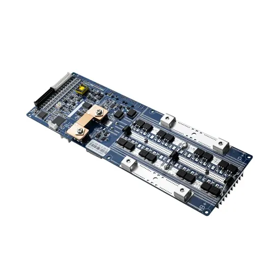
Ranking of portable solar container circuit board manufacturers
This comprehensive analysis ranks the top 10 BESS manufacturers based on production capacity, global market presence, technological advancements, and notable project implementations. Page 1/2 Ranking of portable energy storage circuit board manufacturers. The solar container market is projected to reach USD 0.83 billion by 2030 from an estimated USD 0.29 billion in 2025, registering a CAGR of 23.8% during the forecast period. The market is witnessing rapid adoption due to increasing demand for decentralized and portable renewable energy solutions. . Solar containers - known also as Trailer Accumulating Systems (TAS) are being used more and more as a simple but effective means of power generation for everything, from homes to schools with the year 2024 looming around. They are basically enormous boxes that use the sun to create electric power. . This section provides an overview for printed circuit boards (pcb) as well as their applications and principles. Also, please take a look at the list of 19 printed circuit board (pcb) manufacturers and their company rankings. Here are the top-ranked printed circuit board (pcb) companies as of. . Having hundreds of suppliers who provide quick-turn prototypes and aerospace-grade boards, how can you be sure of which one will suit your needs? In this guide, we have gathered the 10 best PCB manufacturers in USA in 2025, according to their reputation in the industry, capabilities, certifications. . Over 3,100 PCB fabrication, assembly and design companies listed Find PCB Handling, Soldering, Fabrication and Testing Equipment from the leading manufacturers Fill 1 Form and Get PCB Quotes from up to 10 Relevant Manufacturers. What are Space-Qualified PCBs? What are space-qualified PCBs? What are. . This comprehensive analysis ranks the top 10 BESS manufacturers based on production capacity, global market presence, technological advancements, and notable project implementations. Page 1/2 Ranking of portable energy storage circuit board manufacturers Image credit: Jackery Jackery''''s portable.
Read More
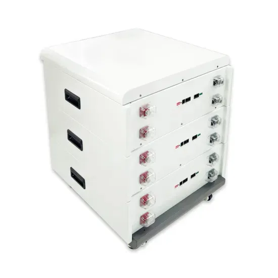
What are the solar container components in the circuit
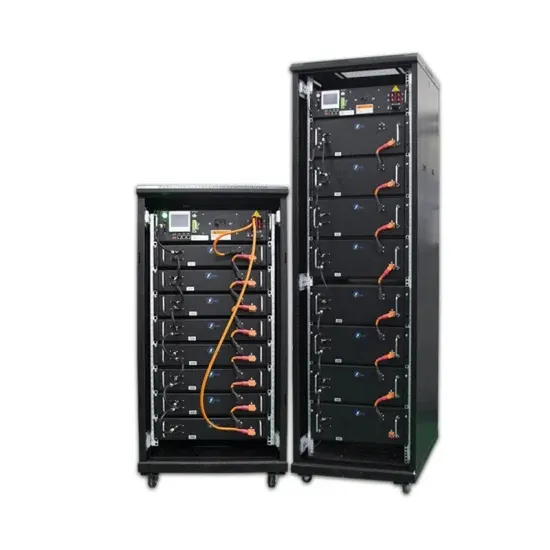
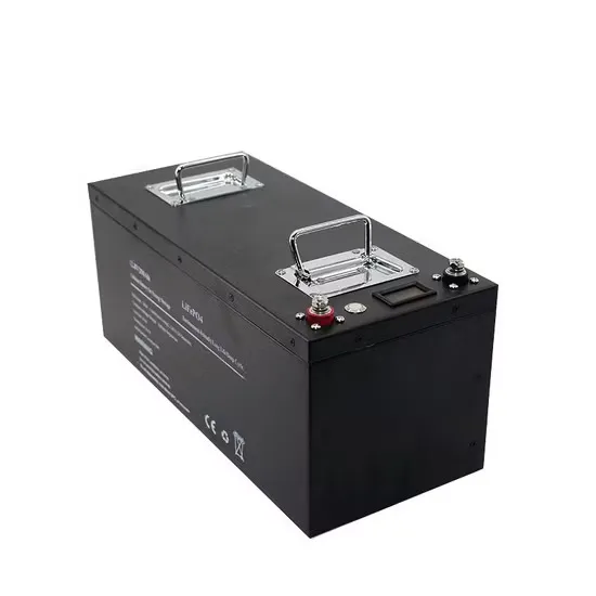
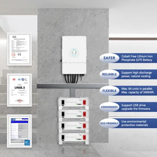
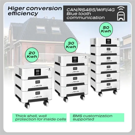
These are solar panels, charge controller, battery storage, inverter, and monitoring system. Each part does something important. Solar panels grab sunlight and make electricity. The charge controller makes sure the battery gets the right amount of power. [pdf]. What are the components of a solar power system? The main solar components that come with every solar power system or solar panel kit are: But how do these solar system components convert the sun’s energy into usable electricity for your home or business? On this page, we’ll break down all the. . From portable units to large-scale structures, these self-contained systems offer customizable solutions for generating and storing solar power. In this guide, we'll explore the components, working principle, advantages, applications, and future trends of solar energy containers. Photovoltaic. . The battery module consists of LiFePo4 battery cells. It adopts distributed BMM control system with functions of collecting the battery voltage, battery temperature and battery equalization to ensure the module works effectively and safely. [pdf] These are solar panels, charge controller, battery. . You need five main solar system parts for a strong off grid solar system in a container: Each part works with the others to give you steady power and real energy freedom. MEOX ’s new Mobile Solar Container puts these parts together for a trustworthy off grid solar system. If you want an off grid. . In order to ensure maximum performance and availability during the lifetime of a solar substation, we offer various options for life-cycle support, from basic maintenance to 24/7 protection and multiple after-sales packages. 1.1 Fast deployment and delivery Eaton offers highly-reliable and. . By the end of this article, you’ll know what each solar component does—from panels and inverters to batteries, controllers, wiring, and mounting systems—and why it matters for your setup. We’ve broken everything down based on real-world performance, safety, and ease of use, so you can make smart.
Read More
Circuit breaker solar container timeout requirements
Fully tested, met and exceeded to the requirements of UL 489B: operating at 1.35 x In (1.35 times the nominal current) within 1 or 2 hours depending on amp rating (50A or less or over 50A respectively) and calibrated at 50°C ambient temperature.. To properly size DC circuit breakers for solar PV systems, you need to calculate 125% of the maximum short circuit current 1 (Isc), ensure the voltage rating 2 exceeds the maximum system voltage 3 with temperature corrections, and use breakers specifically rated for DC applications. For systems. . Choosing the right circuit breaker for a solar PV system is critical. A circuit breaker protects the system from overloads and short circuits, preventing fires and damage to panels, inverters, and wiring. Using a breaker that is too small can cause it to trip constantly; one that is too large won’t. . Fully tested to the requirements of IEC 60269-6 and exceed the requirements of operating at 1.45 x In (1.45 times the nominal current). They also meet the requirements of UL 2579 that are very similar to the IEC standards, except they operate at 1.35 x In (1.35 times the nominal current). The. . Calculate your shipping container home’s electrical panel size, circuit breakers, inverter capacity, and solar panel requirements. NEC 2023 compliant for all 50 states. This container home electrical calculator provides estimates only. Always consult a licensed electrician and structural engineer. . Sizing fuses and circuit breakers correctly is essential for solar power system safety and protection. Solar systems require overcurrent protection devices at three critical locations: between solar panels and charge controller, between charge controller and battery, and between battery and. . Sunpeace DC circuit breakers handle up to 6000A breaking capacity for commercial solar arrays. How Do DC Circuit Breakers Work in Solar Systems? DC circuit breakers handle the specific requirements of solar DC circuits. These devices must interrupt DC current without the natural zero-crossing that.
Read More