SOLAR PV SYSTEM PROTECTION A COMPLETE GUIDE TO DCAC CIRCUIT
Illustrated complete guide to the working principle of solar container equipment
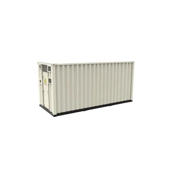
Explore a step-by-step breakdown of how solar containers harness and store solar energy. Understand the process of converting sunlight into DC electricity through photovoltaic panels. Learn how charge controllers and battery packs ensure continuous power availability.. ble energy solutionwith numerous advantages. Despite initial cost considerations and power limita ions,their benefits outweigh the challenges. As technology continues to advance and adoption expands globally,th ions for generating and storing solar power. In this guide, we'll explore the. . Discover the numerous advantages of solar energy containers as a popular renewable energy source. From portable units to large-scale structures, these self-contained systems offer customizable solutions for generating and storing solar power. In this guide, we'll explore the components, working. . Solar power containers combine solar photovoltaic (PV) systems, battery storage, inverters, and auxiliary components into a self-contained shipping container. By integrating all necessary equipment within a transportable structure, these units provide modular, plug-and-play renewable energy systems. . Our Solar Containers are designed in a way to maximize ease of operation. It’s not only meant to transport PVs but also to unfold them on site. It is based on a 20’ sea container. The efficient hydraulic system helps quickly prepare the Solar to work. Because of their construction, our containers. . But what exactly is a solar energy container, and how does it work? Let’s dive into this transformative technology that’s helping to reshape energy accessibility around the world. A solar energy container is a self-contained, pre-fabricated unit—typically housed within a standard shipping. . From portable units to large-scale structures, these self-contained systems offer customizable solutions for generating and storing solar power. In this guide, we'll explore the components, working principle, advantages, applications, and future trends of solar energy containers. Section 1:.
Read More
Solar container battery production protection requirements
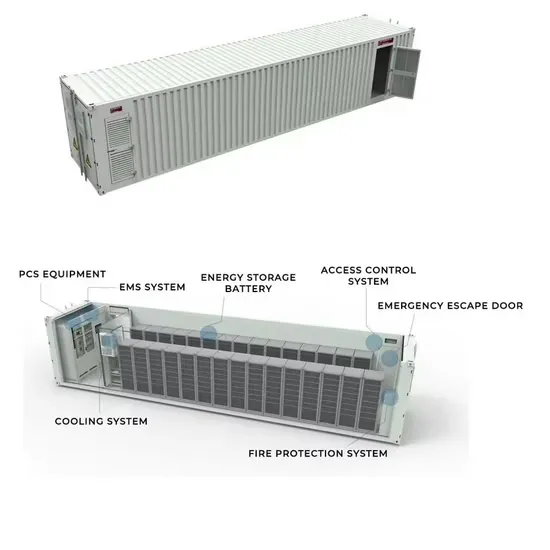
Examples of building codes include requirements for fire suppression systems, ventilation, electrical safety and more. NFPA standards: The NFPA has specific standards for BESS, including NFPA 855 and NFPA 70, which address fire safety, installation and operation.. An overview of the relevant codes and standards governing the safe deployment of utility-scale battery energy storage systems in the United States. This document offers a curated overview of the relevant codes and standards (C+S) governing the safe deployment of utility-scale battery energy storage. . The regulatory and compliance landscape for battery energy storage is complex and varies significantly across jurisdictions, types of systems and the applications they are used in. Technological innovation, as well as new challenges with interoperability and system-level integration, can also. . NFPA is keeping pace with the surge in energy storage and solar technology by undertaking initiatives including training, standards development, and research so that various stakeholders can safely embrace renewable energy sources and respond if potential new hazards arise. NFPA Standards that. . Battery Energy Storage Systems, or BESS, help stabilize electrical grids by providing steady power flow despite fluctuations from inconsistent generation of renewable energy sources and other disruptions. While BESS technology is designed to bolster grid reliability, lithium battery fires at some. . A.EnergyStorageSystemtechnicalspecications B. BESS container and logistics C. BESS supplier’s company information 4. SUPPLIER SELECTION 5. CONTRACTUALIZATION 6. MANUFACTURING A. Battery manufacturing and testing B. PCS manufacturing and testing C. Container assembly 7. FACTORY ACCEPTANCE TESTING. . Provisions appropriate to the battery technology shall be made for sufficient diffusion and ventilation of gases from the battery, if present, to prevent the accumulation of an explosive mixture. Informational Note No. 1: See NFPA 1-2018, Fire Code, Chapter 52, for ventilation considerations for.
Read More
What are the solar container components in the circuit
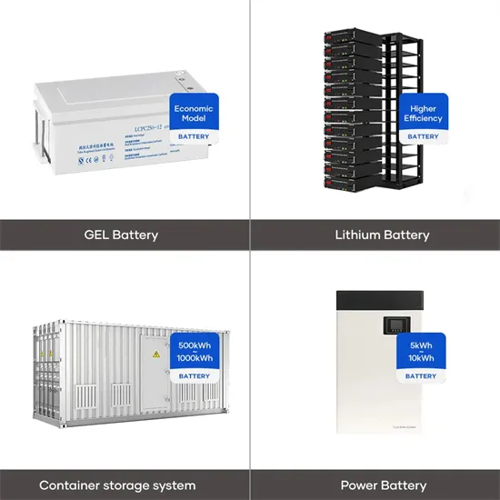
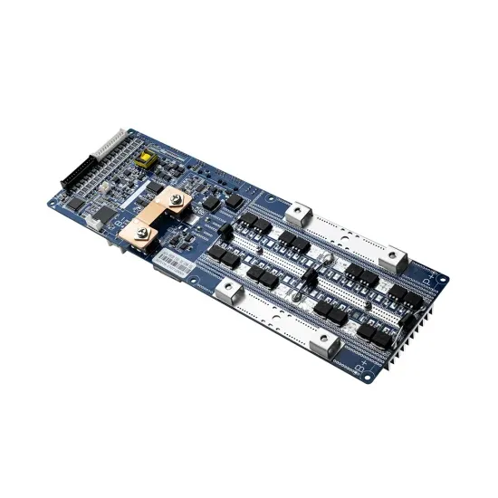
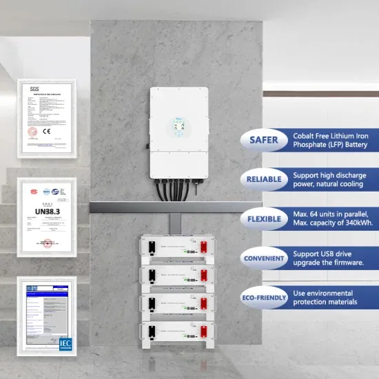
These are solar panels, charge controller, battery storage, inverter, and monitoring system. Each part does something important. Solar panels grab sunlight and make electricity. The charge controller makes sure the battery gets the right amount of power. [pdf]. What are the components of a solar power system? The main solar components that come with every solar power system or solar panel kit are: But how do these solar system components convert the sun’s energy into usable electricity for your home or business? On this page, we’ll break down all the. . From portable units to large-scale structures, these self-contained systems offer customizable solutions for generating and storing solar power. In this guide, we'll explore the components, working principle, advantages, applications, and future trends of solar energy containers. Photovoltaic. . The battery module consists of LiFePo4 battery cells. It adopts distributed BMM control system with functions of collecting the battery voltage, battery temperature and battery equalization to ensure the module works effectively and safely. [pdf] These are solar panels, charge controller, battery. . You need five main solar system parts for a strong off grid solar system in a container: Each part works with the others to give you steady power and real energy freedom. MEOX ’s new Mobile Solar Container puts these parts together for a trustworthy off grid solar system. If you want an off grid. . In order to ensure maximum performance and availability during the lifetime of a solar substation, we offer various options for life-cycle support, from basic maintenance to 24/7 protection and multiple after-sales packages. 1.1 Fast deployment and delivery Eaton offers highly-reliable and. . By the end of this article, you’ll know what each solar component does—from panels and inverters to batteries, controllers, wiring, and mounting systems—and why it matters for your setup. We’ve broken everything down based on real-world performance, safety, and ease of use, so you can make smart.
Read More
Permanent magnetic circuit breaker solar container capacitor capacitance
In this paper we will be discussing about a new smart high performance Circuit Breaker capable of providing extended capacitive current switching performance for protection and control of capacitive loads without inrush current and voltage transients.. In this paper we will be discussing about a new smart high performance Circuit Breaker capable of providing extended capacitive current switching performance for protection and control of capacitive loads without inrush current and voltage transients. In today’s power distribution architecture and. . Eaton offers the industry’s most complete and reliable circuit protection for PV balance of system, from fuses, fuse holders and circuit breakers to safety switches and surge protection—allowing for comprehensive overcurrent and overvoltage protection anywhere in the PV system. Eaton offers a range. . A capacitor is a passive electronic component that stores energy in an electric field. It consists of two conductive plates separated by an insulating material known as a dielectric. When a voltage is applied across the plates, electric charge accumulates, allowing the capacitor to temporarily. . SRIWIN ELECTRIC, an ISO 9001-2015 certified company, offers a unique, space–saving, permanent magnetic actuator operated, outdoor, Pole/Structure mounted, three-pole, gang-operated Vacuum Circuit Breakers, that are a perfect replacement for conventional Porcelain-clad Circuit Breakers. These VCBs. . Abstract—In order to ensure a large-scale application of PV generators in MV distribution system without unacceptable voltage changes due to drops of PV power output a simple, low-cost solution is developed. The solution includes operation of PV with predetermined leading power factor and addition. . The finite element model of the fast operating mechanism is established by using ANSYS Maxwell, and the static and dynamic simulation calculations are carried out, so that the designed fast operating a?| The main differences between thermal magnetic circuit breakers and electromagnetic circuit.
Read More
Rl circuit inductor solar container
Figure 1 shows a switching circuit that can be used to examine current through an inductor as a function of time. Figure 1. (a) An RL circuit with a switch to turn current on and off. When in position 1, the battery, resistor, and inductor are in series and a current. . A resistor–inductor circuit (RL circuit), or RL filter or RL network, is an electric circuit composed of resistors and inductors driven by a voltage or current source. [1] A first-order RL circuit is composed of one resistor and one inductor, either in series driven by a voltage source or in. . To understand the current amplitude behavior of RL circuits under applied alternating current voltages. You have studied the behavior of RC circuits under both direct and alternating current conditions. The nal passive component we must consider is the inductor. The voltage across a capacitor is. . A circuit with resistance and self-inductance is known as an RL circuit. Figure 14.12 (a) shows an RL circuit consisting of a resistor, an inductor, a constant source of emf, and switches S 1 and S 2 When S 1 is closed, the circuit is equivalent to a single-loop circuit consisting of a resistor and. . RL Circuit Definition: An RL circuit is defined as an electrical circuit with a resistor and an inductor connected in series, driven by a voltage or current source. Phasor Diagram: A phasor diagram shows the phase relationships between the voltage and current in the resistor and inductor.. An RL circuit, also referred to as a resistor-inductor circuit, plays a foundational role in electrical engineering and inductive elements. In this Article, We will be going through the RL Circuit, We First go through What is the RL Circuit, and We will see RL circuit formulas, Waveforms, and Power. . the coils for inductors L1 and L2 respectively, and i1 and i2 are the current through the respective inductors. Φ12 is the flux passing through coil 1 from the magnetic rcuit below, with two inductors L1 and L2, with mutual inductance nd part follows by a symmetry argument, with a negated value of.
Read More
Rlc circuit who is the solar container element
In RLC circuits—those combinations of Resistors (R), Inductors (L), and Capacitors (C)—the real MVPs are the L and C. Let’s break it down: Inductors store energy in magnetic fields. When current flows through their coiled wires, they build up a magnetic charge—sort of like. . An RLC circuit is an electrical circuit consisting of a resistor (R), an inductor (L), and a capacitor (C), connected in series or in parallel. The name of the circuit is derived from the letters that are used to denote the constituent components of this circuit, where the sequence of the. . Just last month, a Texas solar farm reported 12% efficiency gains simply by optimizing their energy storage elements in inverter circuits. Wait, no—it was actually their capacitor-inductor balancing that did the heavy lifting. Renewables aren’t like stable grid power. Solar panels create DC power. . Here in this article, we are going to know the uses, applications, and practical real-life examples of RL, RC, LC, and RLC Circuits. Before going to examples first of all we must know about these circuits. The 'RL' where R indicates the resistance and the L indicates the Inductance, so the RL. . e of the capacitor component. The properties of the parallel RLC circuit can be obtained from t SMES components are depicted. It is primarily made up of three components: a cryogenic refrigerator, a low- and high-temperature superconducting coil magnet, a d helium/nitrogen liquid. . While the. . Series RLC circuits consist of a resistance, a capacitance and an inductance connected in series across an alternating supply Thus far we have seen that the three basic passive components of: Resistance, Inductance, and Capacitance have very different phase relationships to each other when. . ÎThree identical EMF sources are hooked to a single circuit element, a resistor, a capacitor, or an inductor. The current amplitude is then measured as a function of frequency. Which one of the following curves corresponds to an inductive circuit? ÎBelow are shown the driving emf and current vs.
Read More