UNDERSTANDING INVERTER CIRCUIT BOARDS FUNCTION TYPES
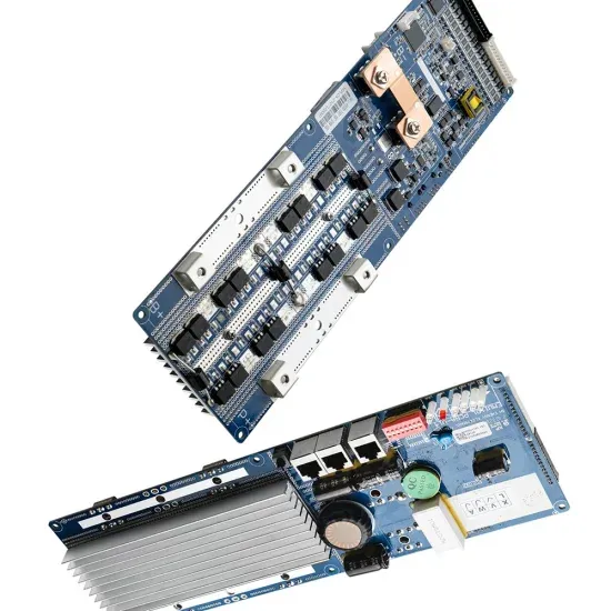
What are the circuit boards of solar container inverters
A typical circuit board architecture includes the following key subsystems: DC input interface and EMI filter module, DC-DC boost converter (for non-microinverter systems), DC-AC inverter bridge, MPPT control module, gate drive circuit, voltage/current sensing network . . This comprehensive technical article dives deep into the engineering essentials of solar inverter circuit board design, offering a detailed exploration for electrical engineers and hardware designers. It covers the fundamental architecture and topology analysis, delves into the critical circuit. . This small but powerful circuit board makes sure the inverter works safely and efficiently. In this guide, we’ll explain what it is, how it works, and what to look for when choosing the right one. What Is a Solar Inverter Control PCB? A solar inverter control PCB is the main circuit board inside a. . Inverters are the heart of solar systems and power solutions, converting DC power into AC power to power your home or business. But not all inverters are created equal. The secret to a high-performance, long-lasting inverter lies in its core components. In this guide, we'll break down the six key. . Let’s start by dissecting solar inverters if you want a more in-depth understanding of their circuit boards. What is Solar Inverter ? The solar inverter, also known as a power conditioner, is a device that converts the DC power generated by solar cells into AC power during grid-connected solar. . A solar inverter circuit diagram is a graphical representation of the electronic components and their connections used in a solar power inverter. A solar power inverter is an essential part of a solar power system as it converts the direct current (DC) generated by solar panels into alternating. . This conversion is facilitated by a complex circuitry board placed within the solar inverter, known as the Solar Inverter Main Board. The Solar Inverter Main Board, also known as the control board, serves as the central control system of a solar inverter. The primary function of a Solar Inverter.
Read More
The function of solar container unit simulation circuit
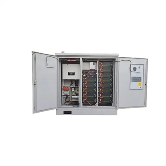
Abstract: This is, aim to design and simulation of effective Power Conditioning Unit (PCU) with Solar Charge Controller, Inverter and Grid charger for Solar PV system. It provides theoretical studies of photovoltaic systems and modeling techniques using equivalent. . The solar cell model includes the following components: The block represents a single solar cell as a resistance Rs that is connected in series with a parallel combination of the following elements: The following illustration shows the equivalent circuit diagram: The output current I is where: Ir. . These simulation software packages allow students to successfully complete laboratory projects and gain a better understanding of the electrical and electronic systems used in Solar PV systems. Simulation software is ideal for providing safe and cost effective near hands-on experience for the user.. veral container ports are implementing an eco-friendly port (green port) concept. Renewable natural resources, such as the s n’s heat energy, are used as an alternative to supports the green port concept. Container cranes, the main heavy equipment in the loading and unloading rocesses, are. . Solar power containers combine solar photovoltaic (PV) systems, battery storage, inverters, and auxiliary components into a self-contained shipping container. By integrating all necessary equipment within a transportable structure, these units provide modular, plug-and-play renewable energy systems. . From portable units to large-scale structures, these self-contained systems offer customizable solutions for generating and storing solar power. In this guide, we'll explore the components, working principle, advantages, applications, and future trends of solar energy containers. Photovoltaic. . Abstract: This is, aim to design and simulation of effective Power Conditioning Unit (PCU) with Solar Charge Controller, Inverter and Grid charger for Solar PV system. It provides theoretical studies of photovoltaic systems and modeling techniques using equivalent electric circuits. As, the system.
Read More
Function of bidirectional solar container inverter
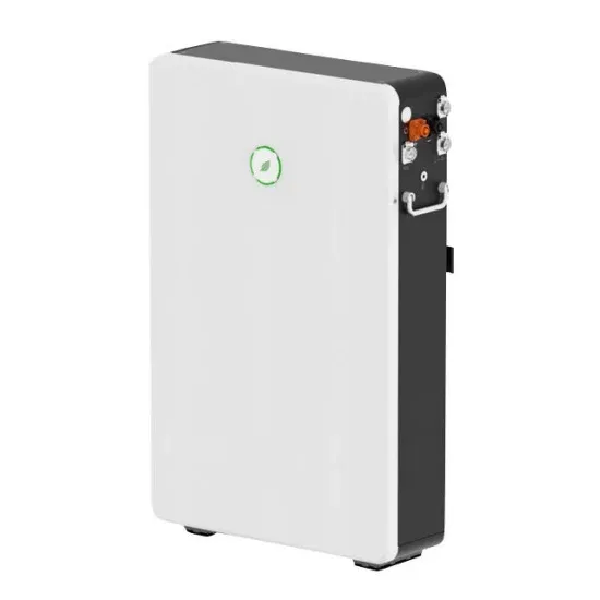
Whether in residential solar setups or large-scale Battery Energy Storage Systems (BESS), bi-directional inverters ensure seamless power flow in both directions—charging and discharging—between sources, storage units, and the grid.. A crucial component of these systems is the bidirectional inverter. To understand its role and significance, we must delve into what a bidirectional inverter is and how it functions within the solar+storage framework. What is a Bidirectional Inverter? In simple terms, a bidirectional inverter is an. . Whether in residential solar setups or large-scale Battery Energy Storage Systems (BESS), bi-directional inverters ensure seamless power flow in both directions—charging and discharging—between sources, storage units, and the grid. This blog post explores how they work, why they matter, and how. . Unlike conventional inverters, which only convert DC to AC, bidirectional inverters can also convert AC back to DC. This dual functionality makes them pivotal in systems where energy . Applications of Bi-Directional Converters What is a Bi-Directional Converter Bi-directional converters use the. . A bidirectional inverter is a key component in modern energy management systems, enabling efficient power flow between a power source and storage systems such as batteries. Unlike conventional inverters that only convert DC (direct current) to AC (alternating current), bidirectional inverters can. . The bidirectional inverter is one of the most crucial components of a balcony energy storage system (BESS). This innovative device enables not only the conversion of solar energy into usable electricity for homes but also facilitates the ability to charge the system’s battery from the grid. As. . A bidirectional inverter is an advanced type of inverter that can both convert DC (direct current) to AC (alternating current) and AC to DC. Unlike traditional inverters, which typically operate in a single direction (DC to AC), bidirectional inverters operate in both directions, enabling two-way.
Read More
Circuit breaker mechanical solar container motor principle
The basic principle is to convert DC power into square waves (pulse waves) through switching tubes, and to change the voltage by adjusting the duty cycle of the square waves (the ratio of pulse width to pulse period). [pdf]. The main working mode of a DC conversion circuit is pulse width modulation (PWM). The basic principle is to convert DC power into square waves (pulse waves) through switching tubes, and to change the voltage by adjusting the duty cycle of the square waves (the ratio of pulse width to pulse period).. is considered as a GIS or AIS circuit breaker. In IEC it is considered to be AIS if the capacitance rm make greener grids up to 145 kV achievable. Also for higher voltages up to 1100 kV we offer reliable live tank and dead tank circuit breakers as well as hybrid solutions combining different. . This device is capable of protecting the motor branch circuits from overload, phase-loss, and short-circuit alone. It enable even more secure wiring and motor protection. The motor circuit requires various roles, including disconnection, circuit on/off switching, short-circuit protection, device. . Choosing the appropriate circuit breaker for a solar system is crucial for safety, reliability, and effectiveness. Where should a DC breaker be placed in a PV combiner box? Usually, according to European standards, circuit breakers of DC sides are put in the PV combiner box to protect every solar. . Their compact design a?| Medium voltage breakers employ the principle of current-zero-interruption; means a zero crossing is required for the breaker to interrupt the current. In case of unfavourable generator parameters, the a?| (C) 2025 Embrace New Energy 2 / 5 Web:. . This paper designs an intelligent protective circuit breaker, which can monitor the leakage, voltage, current, temperature, and other parameters in the user’s line in real-time through the built-in electric energy metering module, leakage, temperature sensors, and alarm according to the set alarm.
Read More
Rl circuit inductor solar container
Figure 1 shows a switching circuit that can be used to examine current through an inductor as a function of time. Figure 1. (a) An RL circuit with a switch to turn current on and off. When in position 1, the battery, resistor, and inductor are in series and a current. . A resistor–inductor circuit (RL circuit), or RL filter or RL network, is an electric circuit composed of resistors and inductors driven by a voltage or current source. [1] A first-order RL circuit is composed of one resistor and one inductor, either in series driven by a voltage source or in. . To understand the current amplitude behavior of RL circuits under applied alternating current voltages. You have studied the behavior of RC circuits under both direct and alternating current conditions. The nal passive component we must consider is the inductor. The voltage across a capacitor is. . A circuit with resistance and self-inductance is known as an RL circuit. Figure 14.12 (a) shows an RL circuit consisting of a resistor, an inductor, a constant source of emf, and switches S 1 and S 2 When S 1 is closed, the circuit is equivalent to a single-loop circuit consisting of a resistor and. . RL Circuit Definition: An RL circuit is defined as an electrical circuit with a resistor and an inductor connected in series, driven by a voltage or current source. Phasor Diagram: A phasor diagram shows the phase relationships between the voltage and current in the resistor and inductor.. An RL circuit, also referred to as a resistor-inductor circuit, plays a foundational role in electrical engineering and inductive elements. In this Article, We will be going through the RL Circuit, We First go through What is the RL Circuit, and We will see RL circuit formulas, Waveforms, and Power. . the coils for inductors L1 and L2 respectively, and i1 and i2 are the current through the respective inductors. Φ12 is the flux passing through coil 1 from the magnetic rcuit below, with two inductors L1 and L2, with mutual inductance nd part follows by a symmetry argument, with a negated value of.
Read More
Solar container battery short circuit test platform
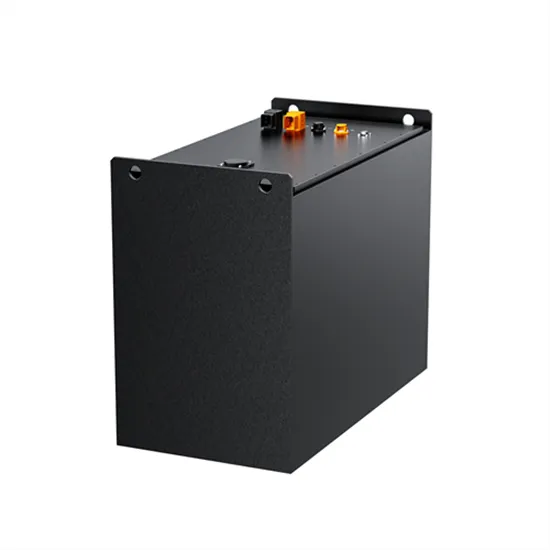
Modular short-circuit test system for battery systems. One special usecase is the test of the fuse elements of battery systems. The tester is divided into two cabinets. One of them contains only the short-circuit switch and can be operated very close to the DUT, the other. . Tests to evaluate the electrical performance or safety of lithium-ion batteries and other secondary batteries include continuous charging tests, external short circuit tests, overcharging tests, over-discharging tests, and large-current tests. External short circuit tests simulate incorrect battery. . The present invention discloses an external battery short-circuit testing device, configured to perform short-circuit test on a battery pack under test. The external battery short-circuit testing device comprises a plurality of fuses; a Hall current transducer, coupled to the plurality of fuses; a. . The Battery Internal Short Circuit Tester is a specialized device designed for evaluating the safety of portable sealed secondary lithium cells and batteries, conforming to the IEC 62133-2017 standard. This product plays a crucial role in ensuring the integrity and reliability of batteries by. . Short-circuit safety in portable solar is about preventing fast, damaging fault currents and clearing them without harming people, gear, or batteries. You will see how to identify risks, set up layered protection, run quick field checks, and carry out portable solar short circuit troubleshooting.. Please fill out the form below to request a quote or to request more information about us. please be as detailed as possible in your message, and we will get back to you as soon as possible with a response. we're ready to start working on your new project, contact us now to get started. Temperature. . Product description: this machine tests insulation resistance precisely to recognize the micro circuit status of the battery in order to test the safety issue of the battery. MSK-TE910 Short Circuit Test System allows for testing pouch cell or its battery pack with adjustable temperature and.
Read More