Inductor solar container voltage direction
HOME / Inductor solar container voltage direction
Let's see what our partners have to say.
PDF Resource Download Center
Access and study high-quality learning materials anytime, anywhere
Introduction
This report presents the design and implementation of a bidirectional four-switch synchronous buck-boost DC-DC converter for standalone solar battery charging applications. The converter enables efficient bidirectional power flow between a photovoltaic (PV) source and a 12 V. Power inductor specifications typically include inductance value (mH),rated current (A),saturation current (A),and DCR (mO)as the main parameters. Inductors,as key components in electronic circuits,can be classified into various types based on structure,manufacturing process,and application. The voltage across gradually changes according to exponential equations while the inductor is charging and discharging. Suppose the inductor has no energy stored initially. At some point in time, the switch is moved to position 1; the moment is called time t=0. How does an inductor store energy?. Assuming my understanding of the above is correct, adding negative VARs (adding capacitance) would usually have the effect of raising voltage levels due to most grids having some degree of a lagging power factor. By adding the capacitance, the lagging power factor is brought closer to unity. This. This report presents the design and implementation of a bidirectional four-switch synchronous buck-boost DC-DC converter for standalone solar battery charging applications. The converter enables efficient bidirectional power flow between a photovoltaic (PV) source and a 12 V lead-acid battery. While there is no defined electric polarity for inductors, direction of current does matter because of a phenomenon called inductor kickback. Kickback occurs when a very high voltage (thousands to tens of thousands of volts) is generated after applying voltage due to the magnetic fields breaking. How do you calculate current through and voltage across an inductor? The current through and voltage across the inductor are calculated by the scenarios detailed from Equation 14.5.3 and Equation 14.5.5. (0) = 0. At t = 2.0 (∞) | = 0. If the time of the measurement were much larger than the time.
Inductor solar container voltage direction
Positive and negative VARs and Solar inverter Grid connect schemas
The voltage is higher at its terminals than at the service disconnect because of voltage drop in the conductors, but if the conductors were superconductors with zero resistance (no voltage
More
Mos solar container inductor
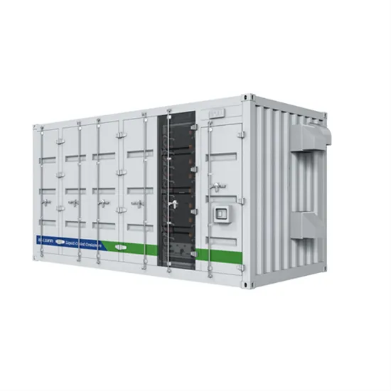
The Solarcontainer is a photovoltaic power plantthat was specially developed as a mobile power generator with collapsible PV modules as a mobile solar system,a grid-independent solution
More
What effect does the installation angle and direction of the Solar
The installation angle and orientation of a Solar Power Container —typically referring to an integrated system combining solar panels and associated components—have a decisive impact
More
Basic Facts about Inductors [Lesson 1] Overview of inductors
Before overcoming the induced voltage that is attempting to block the current, the direction of the current is reversed so that there is no flow of current. The current level remains
More
Inductor Voltage and Current Relationship | Inductors
Voltage Drop Across an Inductor With a Variable, Increasing Current Changing the rate of current increase through the inductor by moving the potentiometer wiper
More
Solar container inductor discharge current direction
How does voltage change during charging and discharging of an inductor? The voltage across gradually changes according to exponential equations while the inductor is charging and discharging.
More
A Practical Guide to Inductors and Inductance
Learn about inductance, different types of inductors, how to calculate current and voltage across an inductor, how to build wire coil inductors, and factors that
More
Solar container inductor parameters
Specifically, we explore how the planar air-core inductor design can be adjusted to achieve the desired inductor performance and evaluate the feasibility of integrating these inductors
More
SOLAR CONTAINER INDUCTOR ZERO CROSSING
This work presents an automatic method and circuit to indirectly detect the inductor-current zero-crossing event in an onchip switching power buck converter operating under Pulse Frequency
More
Understanding Power Inductor Parameters
We offer our expertise and training free of charge, and believe that making the content of, "Understanding Power Inductor Parameters" ("Webinar") on 6/7/2022 available for future use may be
More
The Fundamentals of Power Inductors
Data Sheet Dangers: An Illustration A key component of DC-DC converters, the power inductor has a significant impact on eficiency, transient response, overcurrent protection and physical size. Only
More
Inductor Behavior : Why Orientation Does Not Matter
Regardless of inductor winding direction and orientation, the polarization of the magnetic fields does not matter for kickback because the current resulting from the voltage produced across
More
Field Insights on 3-Phase Inductors for Solar Projects in Utility-Scale
Explore EPC field insights on 3-Phase Inductors for Solar Projects that improve thermal stability, extend inverter life, and minimize operational downtime.
More
DC CIRCUITS CAPACITORS AND INDUCTORS | Solar Power
Here are some key points about it12345:Inductors store energy as a magnetic field.The energy is released quickly when the circuit is turned off or power is lost ductors prevent ripples from
More
Circuit inductor solar container formula
How do you calculate current through and voltage across an inductor? The current through and voltage across the inductor are calculated by the scenarios detailed from Equation 14.5.3 and Equation 14.5.5.
More
EXPERIMENT 3 INDUCTORS AND TRANSFORMERS
This report presents the design and implementation of a bidirectional four-switch synchronous buck-boost DC-DC converter for standalone solar battery charging applications. The converter enables
More
A coupled inductor based high gain Z source DC DC converter with
This work proposes a new, non-isolated, high-gain, and highly efficient DC–DC converter that uses active linked inductor impedance source to boost a solar panel''s output power.
More
Mos solar container inductor
This work proposes an efficient configuration for a solar-powered on-board charging system utilizing a coupled inductor high-gain converter with Grid-to-Vehicle (G2 V) and Vehicle-to-Grid (V2 G) operations.
More
There are direction identification markings on some
An inductor has a winding direction (polarity), and the marking is placed so that the polarity can be confirmed from its external appearance. Depending on usage
More
Solar container power chip inductor customization
An inductor is one of the three passive circuit elements used in electronics. | Chip inductors are typically small, optimized, high-frequency, or radio-frequency inductors for use in
More